EFI Fuel Lines and Injectors
Joe Angell
My 3.0L engine was going to utilize MegaSquirt for EFI. This aftermarket system is commonly used by DeLorean owners to add EFI to their cars, and is very well documented with good community support.
The 3.0L intake manifold is much different from the 2.8L one, notably in that it is designed for EFI. I had initially started on a 2.8L conversion before I found a hole in my engine block, and detailed some of my research in case it helps anyone else.
Throttles
Josh upgraded the throttles for me with a larger unit from a 4.0L Jeep. It has a similar bore to the 3.0L one and it perfectly fits the idle air motor, which itself is from a 4.0L Jeep. He had a custom adaptor plate machined to connect it to the elbow. of the intake manifold. If you're handle I expect you could mill one yourself with hand or power tools, or just use the stock throttles. I reattached the elbow's three bolts to the manifold with a 13mm socket and open wrench.
The adaptor plate that allows the 4.0L Jeep throttle to mount to elbow can be sen sandwiched between the other two parts.
Attaching the throttles with an 13mm socket.
Fuel Injectors
The fuel injectors I got from Josh in the big box of EFI parts are EV-6 style, which are technically not correct for the EV-1 rail, but they fit decently enough that I'm not worried about it.
The first step was to remove the old ones from the rail. I already had the rail off the manifold (four bolts removed with an 11mm socket, and unplug the vacuum hose from the fuel pressure regulator), with some force required to pop the injectors out of the manifold due to the tight O-rings. On the rail side, they are held in place with clips that grab the top of each injector, with a hole in the top of the clip fitting into a raised bit on the rail. To get to the clip, I had to remove the electrical connector. These are similar to other connectors used in the K-Jet system on the DeLorean, and I wound up using a pick to pull the metal band free so that I could remove the connector itself. With the connector clear, I could use a pick to slip the clip off. The injectors themselves were still wedged in quite tightly, and I had to grab them with an adjustable wrench and pry them out. In some cases the O-rings were stuck in the rails or manifold and had to be popped out with a pick.
The new injectors have a USCAR style fuel connectors, which Josh included for me. It was surprisingly difficult to get the connectors off. I figured I'd pull the green tab up and it would slide off, but no go -- I had to use a pick to pull the housing out a little so that it would slip over the nub on the injector and release. Once I figured that out, it was pretty easy.
The connector had to be taken off in order to fit the injectors in the rail. As I mentioned before, these injectors aren't quit the right ones for this rail, so it's a bit of a tight fit. I also had some trouble with the clips for the same reason. The clips that came with the injectors weren't useful as they didn't mount to this fuel rail, but the slot in the injectors was a little too low for the original clips. Still, I was able to force them on well enough by slipping them partially on to the injector, then tipping the injector back until I could slip the clip onto the raised bit on the rail, and finally slide the clip onto the injector the rest of the way. That said, I think the clips are optional, as a 2.8L conversion would have relied entirely on the bolts that hold the fuel rails down to keep the injectors in place. With the injectors in place, I pushed on the connectors, which rubbed against the clips a bit but weren't a real problem to install.
Once that was taken care of, I fit the injectors into the manifold and bolted the entire assembly down with the four bolts and an 11mm socket.
Using a pick to remove the clip around one of the original injectors.
Separating the fuel injector from its connector.
A new injector (foreground left) clipped onto the rail ahead of the old injectors (background right).
The injectors installed on in the manifold.
Fuel Pressure Regulator
Since the 3.0L engine already had a perfectly good fuel pressure regulator, I decided to keep it. Fuel feeds into the passenger side rail, then runs along through a fuel line to the other rail before exiting from another fuel line to the regulator. There's also a vacuum line connected to the regulator for reasons that I'm not clear on. The hoses were a bit hard, but seemed to be in good shape. I decided not to press my luck by trying to pull them off.
Tightening the fuel rail onto the intake manifold. The fuel pressure regulator is the cylinder next to the fuel rail on the left with the rubber lines connected to it..
Feed and Return Fittings
I was building my own AN-6 fuel lines, so I needed to adapt the GM-style clip fittings to support those connections. After much searching I found the two I needed from JEGS:
555-103100 AN-6 Male to 5/15" FI LTI (Return Line)
555-103101 AN-6 Male to 3/8" FI LTI (Feed Line)
The larger one is the feed line, and is used to adapt the fuel filter to the fuel rail. The smaller one is the return line, and runs from the fuel pressure regulator back to the tank.
My next task was figuring out how to get these on. The old plastic connectors that were on the rails came off easily: squeeze the two plastic tabs and it slides right off. My new metal connectors were another story -- they refused to slide onto the rails. i finally resorted to screwing a fuel fitting onto the connector, resting a block of wood on it, and tapping it a few times with a hammer. This did the trick, although I have no idea how I'll ever get it off again should the need arise.
Pinch the plastic clip and slide the connector back off the rail.
Getting the new metal connector on involve a rubber mallet (top), a piece of wood (middle), a fuel fitting (red/blue) and the connector itself (black) on the end of the rail (bottom).
Reinstalling the Intake Manifold
With everything mounted to the manifold, it was time to put it back on the engine. The old O-rings were flattened against the heads, so I pulled them out with picks and replaced them with the new ones I got in my DPI gasket kit. After that, it was a simple matter of tightening the four bolts with an 11mm socket, although one required an open end wrench.
Using a pick to remove the old O-rings from the cylinder heads.
Tightening down the intake manifold with an 11mm socket.
The manifold fully installed on the engine.
Oil/Air Separator
This is used by the positive crankcase ventilation (PCV) system to do exactly what it says, separate oil from air that leaks in during combustion. I broke my separator when transporting the engine and have been unable to find a replacement, so I'm reusing the 2.8L engine's oil filler. On the 2.8L engine this serves the dual purpose of separator and oil filler cap, but on the 3.0L it is purely used as a separator. One end of the hoses runs to a nipple on the manifold, while the other runs to the air box. Since I wasn't up to that point yet, I just connected it to the manifold for now.
The oil/air separator from the 2.8L engine installed on the 3.0L engine.
Fuel Pressure Gauge
I had bought a pressure gauge for the 2.8L conversion, so I figured I might as well use it here. It was a 0-100 PSI fuel pressure gauge (JEGS part 555-41023). To attach it to the fuel line, I used an AN-6 Male to AN-6 female adaptor with pressure gauge port (JEGS part 799-670340). I screwed it onto the end of the fuel pressure regulator, since some Googling suggested that the proper location is on after the regulator (as opposed on the feed part of the rail).
The fuel pressure gauge mounted to the outlet of the fuel pressure regulator.
Update: This is completely wrong. By placing the gauge after the distributor, it only showed the pressure of the fuel returning to the tank, which as less than 5 PSI. This of course makes perfect sense in retrospect. The correct location is on the feed line before the fuel rail.
Note that except for the following image, all remaining pictures show the fuel pressure gauge incorrectly mounted after the pressure regulator.
The incorrect and correct installation of the fuel pressure gauge.
Fuel Feed Line
The feed line comes from under the driver's side of the car, and runs through the fuel filter. I had removed mine quite some time ago when i started the engine swap, so I don't have details or pictures to share. I also relocated the fuel filter to the bulkhead in the engine bay for easier access, and made some fuel lines with AN-6 ends. Details of this process and making fuel lines can be found in that blog post. The fuel line from the fuel filter attaches to the end of the driver side fuel rail.
The fuel line under the car, where a 90 degree AN-6 adaptor runs up to the fuel filter.
The fuel filter mounted on the bulkhead, with a fuel line running from it to the end of the fuel rail.
Fuel Return Line
The fuel return line is on the passenger side of the car, and features a banjo bolt to the old K-Jet fuel distributor. I decided to replace that entire line all the way back to where it meets the hardline, similar to what I did with the feed line..
To do this, you need two 17mm wrenches, or one 17mm and one 11/16" wrench to remove the old hose from the hardline. It is also easier to to do this with the engine out of the car, which is when I did it. The hard part was breaking them free. I added a bit of Kroil penetrating oil, but in the end it was brute force with the two wrenches. To get some more leverage (and more comfort) I slide some short pipes over the ends of the wrenches and was finally able to break them free.
Using two wrenches to separate the banjo line from the hardline.
Pipes added leverage and made turning the wrenches more comfortable.
The separated lines.
With that taken care of, I built a new fuel line with AN-6 connections and attached it to the fuel pressure regulator. To mate it to the fuel return line required another AN-6 to AN-5 union reducer (part 361-991907 from JEGS). for some reason I found a 19mm wrench to be too large, and a 17mm to be too small, so I used a used a 15/16" wrench and bolt vice grips to turn the connector. It required quite a bit of force to get it down to the O-ring, but it eventually mated completely.
The return fuel line (red and blue connector) to the hard line dark grey connector) just below the old 2.8L ignition system's coil (red cylinder on the right).
The return line connected to the fuel distributor (center), with the feed line connected to the fuel rail (left).
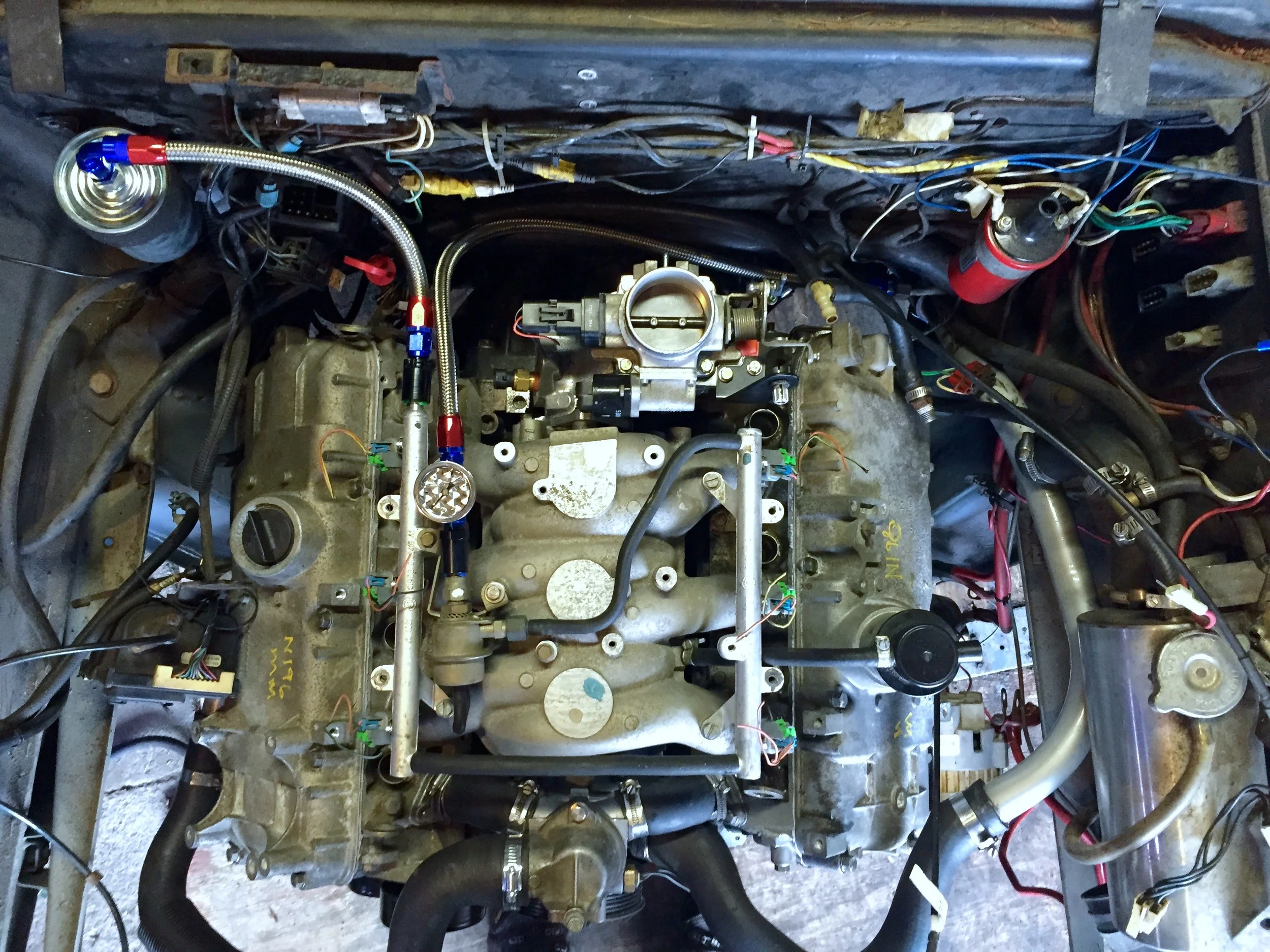
The final fuel system installation from above.
That takes are of the 'fuel" part of EFI; now I just need to do the "electronic" part. Also ignition control, and figuring out how the cold air intake is going to work, but Josh's parts have me mostly covered there.