Reinstalling the Engine and Transmission
Joe Angell
With the frame patched and painted and the new engine refurbished, it was finally time to put everything pack in the car.
Attaching the Flex Plate
Since I have an automatic, there is a flex plate instead of a flywheel that links the engine and transmission. The flex plate is held onto the crank with seven (7) short bolts, and is sandwiched between two flat rings that act as washers. For whatever reason, the holes in the flex plate and rings aren't evenly spaced, and it takes some trial and error to get everything installed properly, mostly flipping the rings and rotating them until the holes line up.
I already had the flex plate mounted from my compression test, but I had misplaced one of the bolts. I ordered six new bolts (having forgotten that there were actually seven), reusing one of the original bolts. I didn't bother to clean off the flex plate or the torque converter; they both had some surface rust, but since they're bolted together the surface quality isn't hugely important (my understanding is that flywheels directly contact the clutch, and a smooth surface is important for manual transmissions). I thought about painting them, but was worried about possible balance issues. I could have had a machine shop mill off the rust, but it really didn't seem like it was worth the trouble, since without paint they would probably rust up again in relatively short order anyway.
Each of the bolts were attached with blue Locktite (which can be removed without a torch, unlike the red flavor) on the threads, and tightened to 42 ft lbs with a 17mm socket. This torque is greater than the engine requires to turn, so I had to wedge a screwdriver between the flex plate and the engine to keep it still.
Installing the new bolts on the flex plate with a 17mm socket and blue Locktite.
Torquing the flex plate bolts, with a screwdriver wedged against the engine to keep the crank from turning while tightening.
Mating the Engine and Transmission
The first step was attaching the transmission to the engine so that they could be put back into the car as a single unit.
As with the temporary mating I did for the compression test, I had to lift the transmission slightly and shim it with a 2x4 so that it would line up properly with the engine. I was then able to raise the engine and align it with the transmission. The upper bolts fit easily enough, but the lower bolts were pretty tight, requiring more torque than I expected to seat them fully. The bolts take a 17mm socket.
I couldn't find values on proper torquing, so I just went to 30 ft lbs, which is the standard value for those size bolts. Once the engine and transmission are bolted into the car it's pretty unlikely that they'll come apart anyway.
Hoisting the transmission and propping it up with a block of wood so that it will align with the engine.
Engine and transmission bolted together.
Attaching the Flex Plate to the Torque Converter
Three bolts attach the flex plate to the torque converter. As with the flex plate crank bolts, these are not evenly spaced, so after attaching the first one you have to rotate the engine to see if the remaining holes line up.
I had a more immediate problem, though: with the bell housing torqued down tightly to the block, the torque converter turned with the flex plate. This made it impossible to line up the holes, and there was no obvious way to keep the torque converter from turning. The only solution I could think of was to separate the engine and transmission again. I had to completely separate them, removing the four mating bolts and lifting the engine free.
To get the holes aligned, first rotated the torque converter by hand (it spun very easily) until one of the bolt holes was visible where the starter would mount. I realigned the engine to the transmission and threaded a couple of the mating bolts through the bell housing and into the block to ensure the flex plate and torque converter were on the same plane. I then used a 35mm socket with a cheater bar to align one of the bolt holes in the flex plate with the torque converter. The cheater bar is handy because it gives you finer control over the rotation of the engine.
Once aligned, I hand-threaded the first bolt, rotated the engine, and threaded the second bolt, and then the third. I got lucky and got the oddly-spaced bolt holes aligned on the first try.
I bolted the bell housing to the engine again, and torqued the bolts, and then went back to the torque converter bolts. I tightened the first one down and torqued it to the recommended 22 to 26 ft lbs with a 17mm socket.
The next problem was when I tried to rotate the engine to torque the other two bolts down -- the engine seized. When I torqued the transmission to engine mating bolts, I pulled the engine and transmission closer together to the point that the bolt heads were sticking out of the flex plate an extra inch or so towards the engine, so much so that they hit the engine when turning the crank.
So once again I unbolted the engine from the transmission, although I only loosened the bolts enough that I could pry the transmission back an inch or two. This allowed the bolts to clear the engine as I turned the crank, and finally torque them down. To keep the engine from rotating as they were torqued I left the on the crank and let it jam against the floor.
With the flex plate finally fastened to the torque converter, I was able to once again torque the bolts through the transmission bell housing to the transmission and finish the mating process.
Tightening one of the bolts that holds the flex plate and torque converter together. A socket only fits at a very specific crank rotation, so I used a box wrench to start.
Torquing the flex plate bolts with a 17mm socket. This is the position the engine has to be in to get the socket to fit on the bolt.
Torquing the Main Crank Pulley Nut
I used blue Locktite on it to avoid it spinning off while on a drive. The manual says to torque it to 135 ft lbs, but my torque wrench only goes to 100, so I decided to tighten it to do it by feel. I locked the engine from rotating with a screwdriver between the flex plate and the block, and used a 35mm socket and a cheater bar to tighten it as much as I thought was appropriate without bending the flex plate itself.
New Automatic Transmission Dipstick
Just an aside here: I snapped off the handle of my transmission dipstick and got a replacement. I used pliers to pull out the old one. I thought it was interesting that there seems to be two styles; my old one is on the right in the pictures below.
Installing the Starter
I decided to reinstall the starter before I put the engine back in the car. My aftermarket high-torque starter's solenoid wire is inconveniently located between the engine and the starter, so I first ran a short length of wire out and attached a female blade connector to it.
Bolting up the starter is easy enough. I interred the original cover/spacer between the starter and the transmission bell housing (plus the two extra spacers that my aftermarket unit needed to keep it from hitting the flex plate when not engaged). This s pretty straight-forward; just three bolts with a 13mm socket. I could find torque values for these bolts, so I just snugged them up as far as I thought was safe.
The starter bolted to the transmission bell housing.
Three bolts holt the starter in place, and are tightened with a 13mm socket.
Replacing the Engine Mounts
My transmission mounts were pretty new, with clean gold paint. The engine mounts were another story. While the rubber seemed OK and the metal appeared to be strong, it was also quite rusty, so I decided to replace them.
The kit sold by DeLorean.com includes one mount, a threaded rod and two nuts and two washers that together create a bolt to hold the engine to the mount. You need two kits, one for each side of the engine. I also ordered four new M8 bolts to hold the mounts to the frame. You can use longer M8 bolts if you have them, as the space inside the subframe is quite deep, but it's easier to use the standard shorter ones to make it easier to get them in and out when the engine is in the car.
Old and new engine mounts.
Another view of the engine mounts.
With the engine out of the car, the mounts are quite easy to replace. A 13mm socket or wrench can be used, although you'll probably have to use the wrench due to space constraints. Mine came out easily. Then you just put the new mounts, making sure you didn't install them upside down, and thread in the new bolts.
Note that at this time you should not torque down the bolts. A little bit of leeway is handy when lowering the engine and getting everything lined up. Once the engine is in, you can torque them down tight, although due to how tight the space is you likely won't be able to use a torque wrench (I didn't even look for torque numbers). I did find a torque number -- 18 ft lbs -- although I"m not sure if that's for the the bolts that hold the mounts to the frame, or the threaded rod that holds the engine to the mounts.
New engine mount partially installed on the frame.
Both mounts installed, but not yet torqued down.
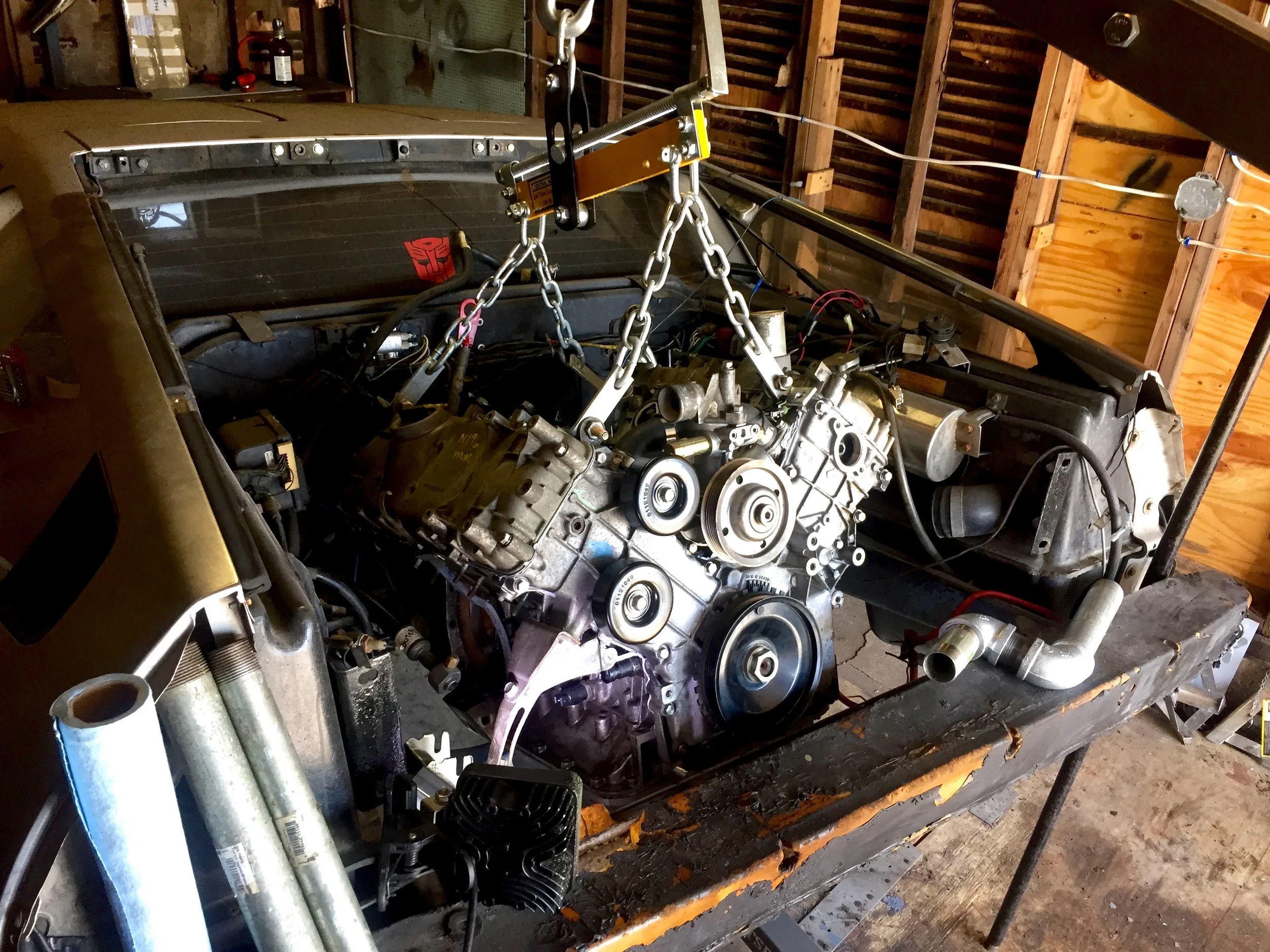
Lifting the Engine and Transmission
Due to the need to accurately tilt the engine, I attached the leveler and used all four chains, instead of just the three I'd used the first time. My new engine was missing a lift ring, so I simply screwed a 13mm bolt and a large washer into the head and used that to anchor the chain. This mostly worked, although the edge of the chain wound up slightly denting the edge of the spark plug cavity. It was not significant, and won't affect operation or sealing. Also, this chain wound up being slightly lower than the others, which affected leveling the engine horizontally a little, but it wound up not being too big of a problem. Finally, one of the rings was bent due to previous lifting, but this was easily rectified with a pry bar.
A bolt through one of the lift rings. The ring was bent back towards the head, but was easily pried back to vertical.
All four chains attached to the block.
With everything hooked up, I was able to lift the engine. I used the 1/2 ton position on my lift to get the maximum height; the combined engine and transmission max at around 800 lbs, so a half ton is enough. After the engine was in the air, I used the crank on the leveler to get it as level as I could, although it still tipped back a little bit due to the weight distribution.
Lifting the engine went smoothly. I had to partially close the garage door to keep the lift's arm from hitting it. I also couldn't easily move the lift by hand, so I used a 6' pipe as a lever to push it around.
Using a pipe as a lever to more easily move the lift around. The lift was pushed so far back that the back wheels were no longer on the plywood I used to create a smoother temporary floor.
The engine lifted and ready to be installed.
Mounting the Engine and Transmission
With the engine and transmission level and raised up above the bumper, the next step was getting it into the engine bay. The first step was easy enough: push them a far back as I could. Once the transmission was over the engine bay, it was time to tilt it by turning the leveler.
With 800 lbs of engine and transmission hanging off of it, the leveler can be very tough to turn. I removed the small handle used a short length of pipe to create one that was easier to grip. This worked pretty well, except when the crank was vertical, as the pipe interfered with the lift arm and required me to turn the crank a few degrees without the pipe. The pipe was still easier than only cranking by hand, though.
Once the engine was partially lowered, I needed to start leveling it out again. It was much harder to turn the crank, and I had to rely on the pipe exclusively. To get around the lift arm, I went to the hardware store and bought two 90 degree bends and three short pieces of pipe, and linked them together into a kind of zig zag shape. This let me use the pipe for the all cranking.
Later, I noticed the 1" bolt on the other end of the leveler. A socket wrench on that was much quicker than using the pipe.
A series of pipes used to make it easier to turn the crank and clear the lift's arm.

Turning the crank with a socket on the 1" nut I didn't notice earlier.
The engine and transmission mostly level over the engine bay.
Starting to tip the engine and transmission down.
The engine partially lowered into the compartment.
At this point, I went back and forth between tilting the engine more level, pushing it back into the engine bay and lowering it into the car. Eventually the transmission was pretty level and just needed to be pushed further back to interface with the mounts.
Before I lowered it all the way, though I needed to route the transmission cable through the frame. This would be pretty hard to do later, so it's a good thing I remembered to do that first. Since I didn't want to be under the transmission while it was being lifted by the hoist, I rolled my creeper in under the side of the car and reached up to slide the cable through the hole near the fuel accumulator.
The engine positioned under the cabin and the engine all the way in the bay.
Routing the transmission cable through the frame before fully installing the transmission itself.
Now it was just a matter of lining up the engine and transmission with their respective mounts. This wound up being a bit more troublesome than I expected. The transmission mounts are vertical blocks of metal, and the transmission has C-like brackets that slide over them. I actually didn't have much trouble getting the right one aligned. The left one was a bit high due to the aforementioned placement one of the leveler chains on the engine, but I compensated for that by jacking up that side of the car a bit more.
The new problem was that while the transmission seemed to line up properly, the engine did not -- there was a good inch or two between the lower crankcase fingers and the engine mounts themselves. The engine and transmission were firmly attached to each other, and with the lower crankcase of the 2.8L engine attached to the 3.0L, this was the exact same configuration as original engine and transmission, so I wasn't quite sure what was going on.
The golden C-like bracket on the transmission mating the mount on the frame behind it. The transmission needs to be shifted a bit to the right so that the holes line up, but otherwise it's in position.

The engine mount is off by more than an inch, though -- it simply won't reach.
I lifted the engine and transmission back out of the car (using the wrench on the leveler nut this time) to get a look the mounts so that I could have a better understanding of how all this went together. I hadn't realized that the transmission mounts sit at about 45 degrees, as opposed to sticking out to the side. Simply aligning the holes in the transmission mounts would push the engine far enough forward to fit the engine its mounts.
The transmission bracket (gold painted, with a hole in the center) sticks out about 45 degrees. The right side of the photo is towards the engine; the "C" like design of the bracket slides over the mount on the frame.
The mount on the frame sits in a block of rubber inside of a gold-painted box. This is what the transmission's bracket lines up with.
Even so, this still wound up being a bit tricky to get everything lined up at once. In the end, I lined up the driver's side transmission mount, then rolled under the car from the side and ran a bolt through it, partially tightening it with a combination of a 17mm socket and a 17mm offset wrench (for whatever reason, the contrived wrench-adaptor-socket combination I had to use when removing the bolt wasn't necessary this time). I then did the same for the passenger side transmission mount.
Still, the engine mounts were a bit too far forward relative to the lower crankcase. Even after tightening the transmission mount bolts down (which pulled the engine a bit further forward) they wouldn't quite line up. I finally solved this by removing the top bolt from each engine mount and rotating it to line up with the crankcase. I also ran the bolts through the crankcase holes at this time, so that they would properly slide into the slot on the mount. I was then able to lower the engine onto the mount without any problem.
Of course, now I needed to get the bolts back in. With the engine slightly raised, a block of wood and a four pound hammer let me tap the driver's side mount until the bolt holes lined up. For the passenger side, I had to raise the engine almost completely clear of the mount before I could bolt it down. I finally lowered them both and used a 17mm socket and wrench to tighten the engine to the mounts, and a 13mm socket to tighten the mounts to the frame. I just got them as tight as seemed reasonable, as I really couldn't get a torque wrench on them properly.
Tightening the transmission to the mounts with two 17mm wrenches (view looking up from below).
The engine sitting on the mount. Notice that the top bolt of the mount is removed for alignment, and the hole in the lower crankcase is slightly offset. I had to raise the engine again to get the bolt through the crankcase.
The engine secured to the mount.
The engine finally sitting securely in the engine bay. Now I just have to hook everything up to it...
Reattaching the Emergency Brake Cable
A graphic I made for the engine removal post showing how to release the emergency brake cable from the bracket.
I had to check my older post about removing the engine and transmission to figure out how to put it back in again. The very strong spring has to be compressed by pushing the two washers against the nut, after which you can slip the cable into the notch on the bracket. I found this very hard to do by hand, and would up using a small split pry bar behind the washers, slipping that up against the bracket, and prying between the bracket and the washers until the spring was compressed enough to slip the cable into the slot in the bracket. Make sure the nut is fully backed off before you try to compress the spring, or you won't get very far.
I next reattached the end of the cable to the brake. It just drops into the hole and is tightened down with an 11mm wrench. Make sure it drops down, with the nut on the bottom; this ensures that if the nut falls off, the cable won't fall out and can still actuate the brake in an emergency.
The last thing is to tighten the nuts that hold the cable to the bracket. This requires two 15mm wrenches. This is also how you adjust the brake. In my case, the nut on the far side of the bracket (towards the center of the car) hadn't rotated, and was slightly rusted in place against the far side of the screw, so I just tightened the other nut against the bracket. I'll have to go back later and make sure the cable is properly adjusted, just to be sure.
The cable reinserted through the slot in the bracket. The slotted pry bar above was used to more easily compress the string to reveal the cable.
Using an 11mm wrench to whiten the end of the cable to the brake.
Two 15mm wrenches are used to tighten the cable against bracket. The brake is adjusted by changing the position of the nuts along the threaded rod through which the cable runs.
Re-Installing the Upper Link Arm
This is a bit of an aside, but I had removed the passenger side upper link arm in order to repair some rust holes in the frame. Reinstalling it was more of a pain than I had expected. It's easy enough to line up one side of the arm to get the bolt into it, but getting the other end lined up so that the bolt will actually go out the other side was quite a bit trickier than I expected.
Inner Alignment
After failing to get the bolt through simply by pushing it in and tapping the arm with a mallet, I removed the bolt and felt around with a long pick. This let me see how the alignment was by feeling around the edges of the hole. If everything was lined up, it would just be a straight shot with no obstructions. I did notice that rotating the arm would adjust the alignment, but I still couldn't quite get it right.
I finally put a 19mm socket no a socket driver on my power screwdriver, put that on the end of the bolt, and let it spin while pushing it towards the arm. While it did this, I swung the arm up and down to adjust the alignment. In just a few seconds the bolt slip through the far end of the arm and grabbed the threads on the frame.
The threads were pretty tight. A lot of heat was generated by tightening the bolt, so I stopped periodically to let it cool down a little. I don't know if it would cause any real problems (people use torches to remove bolts, after all), but I didn't really want to risk damaging anything. Once it was snug, I tightened it to the specced 60 ft lbs.
Outer Alginemnt
I had similar problems with attaching the link arm to the hub carrier. You're fighting the suspension spring and the trailing arm's weight here. I got the basic alignment by jacking the hub carrier up, and then used a rubber mallet to tap the link arm into place before testing the alignment with a pick. This took a few tries before it was good enough to run the bolt through the arm. The fit was pretty tight, so I had to tap it with the side of my mallet to get it in. I soon had to switch to my four pound hammer to get it the rest of the way through. There was so much friction I couldn't spin it with my power screwdriver even while I was still tapping it with the rubber mallet. It seemed that once I had one end aligned, the other end was pretty decently aligned as well and didn't require much fiddling.
Once the bolt was in place, I put on the nut and torqued it 42 ft lbs with a 19mm socket as per the Workshop Manual.
Using a 19mm socket on power screwdriver to turn the bolt. While the driver ran, I tilted the arm up and down until the bolt caught on the threads in the frame.
Torquing the inner link arm bolt. The outer bolt is already run through the arm and hub carrier and ready t one torqued.
Reconnecting the Transmission Cooler and Passenger Coolant Line
The transmission fluid runs through specially-designed pipes along the coolant lines on the passenger side of the car. The engine coolant runs through an inner pipe to the radiator, while the transmission fluid is circulated around and back to the transmission. This keeps the transmission fluid cool. PJ Grady also sells a heat sink to further cool the fluid, thus prolonging the life of the transmission. I've had one installed on my car for a few years now, although mine is a little beat up. Ideally you want the fins to be straight to provide optimal heat dispersal. I'll should probably pick up another one at some point...
I had completely removed the coolant pipe from that side of the car, from the point just ahead of the transmission all the way up to the coolant doddle and the engine. In principle, re-installation is straight forward: slide the pipe in from the top, mate it with the metal coolant pipe coming from the front of the car, and attach the two transmission cooler hoses to it before finally securing the pipe with a bracket and connecting the ends to the coolant bottle and water pump.
Of course, it didn't go that easily. I wound up binding the rearward transmission cooler line to the point that I just assumed I was going to strip the threads in the line. I also wound up bending the metal portion of the line near the transmission. I decided to remove it instead, but my wrench just turned the adaptor on the transmission, and there wasn't enough clearance to turn it around completely from there. I wound up getting out my angle grinder and cutting off the line and ordering a replacement. I had to clamp the adaptor nut into a vice and put quite a lot of torque on the wrench to break it free from the line.
The new line fit much better into the pipe. One end attaches to the topside of the cooler pipe, and the other end into the transmission adaptor. The rubber section is longer, and made of much better material. After checking with Dave Swingle at DeLorean Midwest that it really was the right part, I threaded it into the coolant pipe and then flexed the rubber portion to get it aligned with the adaptor in the transmission. A 7/8" wrench got large the adaptor secured, while a 17mm wrench tightened the the cooler nuts on the lines. The forward cooler hose is the same, mounting on the bottom of the pipe, and went on much easier than my rearward hose.
The old cut transmission cooler line (top) and the replacement (bottom) with its protective caps still attached. The new line is a bit longer than the old one, and needs to be flexed a bit to get it to mount, but it's also much better built.
The new cooler line attached to the pipe. The other end on the left has to mate with the hole visible beneath it in the transmission.
Flexing the cooler line to reach the hole. The strong rubber hose made this a little tricky, but I'm assured that this is correct.
Final installation. The forward line attached to the pipe much more easily.
The forward cooler hose is the same, mounting on the bottom of the pipe, and went on much easier than my rearward hose.
The coolant pipe is held to the frame via a bracket and two bolts, which are secured with an 8mm wrench. The holes are threaded, so there is no nut, just the bolts and their washers. The other ends of the pipe are held onto the coolant bottle and the passenger side of the water pump with hose clamps. This is probably a bit too late to mention that you should make sure that your hose clamps are already in place before putting the hose on. I found that my power screwdriver put out just the right amount of torque to tighten the clamps without stripping them, although in my eagerness to make sure they were right I did wind up stripping one with a socket wrench and had to replace it. Update: Once I added coolant, I found out that they weren't actually tight enough, and I had to use a socket to make sure they really were clamped down properly.
The driver's side coolant lines were much easier. After spending 10 minutes trying to figure out what I did with the plastic pipe line, I found it was still attached to the car and simply pushed out of the way. I grabbed the rubber pipe and used hose clamps to secure it to the plastic pipe and the water heater.
The rear coolant line attached to the bottom of connection on the cooler pipe. This went on much easier.
Securing the coolant pipe to the bracket with an 8mm socket.
Final installation. I should probably get a new heat sink from PJ Grady; mine's getting a bit beat up.
One final thing to do: tighten the brackets holding the coolant lines ahead of the transmission with a 11mm socket.
Attaching the Transmission Cable Linkage
I had disconnected the transmission from the crossover arm inside the cavity in the frame where the fuel accumulator sits. This was relatively easy: a nut holds cable to the crossover arm, and the two bolts hold the cable in place with a bracket.
The first problem was that I dropped the nut inside the cavity after slipping the bolt into the crossover. After failing to retrieve it with magnetic tools and a clasper, I realized I had some extra M7 nylock nuts and just put a new one on. I used a 13mm socket to install it instead of a box wrench, just so I wouldn't drop the wrench in there as well.
The next problem was the brackets for the transmission cable. It wasn't so much the brackets, but the nuts the bolts are supposed to go into. See, in most cars they're welded to the frame. In my car, they were not. It actually took some time to get them out in the first place, wedging a wrench between the frame and the body to reach into the gap and grab the nuts while turning the bolts with a wrench from inside the the cavity.
The correct fix for this is to lift the body off the frame and weld the nuts in place with electric welding equipment. I wasn't going to do that. I briefly considered zip-tying the bracket through the bolt holes, but I wasn't sure that would be enough and wasn't confident that I could get the zip tie back through the second hole.
My solution was to use a piece of flat aluminum stock to make something to replace the nuts. I used the bracket as a template and drilled two holes very near one edge, and threaded it with an M8 tap. I then bent a few inches from the hole end so that it matched the curve of the frame, and then cut it off a few inches after that. This gave me a new backing to screw the bracket bolts into.
I then spent at least twenty minutes fiddling with getting my new backing and the bolts aligned with the holes in the frame. You can't see the bolts in inside the cavity, and you can't see the backing when it's inserted between the frame and body, so you have to do it entirely by feel. But I did finally get everything in place and tightened down.
Next time, I'm going to disconnect the cable at the transmission instead.
Drilling holes into my aluminum stock for the backing to replace the nuts fro the transmission cable bracket.
Tapping new holes into the backing.
Final installation. The end of the backing sticks out a bit and presses against the aluminum, but it shouldn't move much and should be fairly stable.
Capping the Distributor Hole
Since I'm not using the distributor on the 3.0L engine, I needed to cap the hole in the end of the cylinder head so that all their didn't splash out. It turns out the can access cover for the 2.8L engine and an O-ring perfectly seal the hole. The only problem is that one of the holes doesn't line up. I fixed this by clamping the cap in a vice and drilling successively larger holes until I was at the size I needed, and then joining the two holes by pushing the bit against the edge of one hole until it ground through to the other one. This gave me the extra distance I needed reach the bolt hole and secure the cap to the block. The cap is secured with two bolts and a 13mm socket.
Update: DeLorean Performance Industries sells a distributor block-off plate specifically for this purpose, if you want to save yourself some trouble.
The extra hole drilled into the cap and joined with the original hole, creating a slot.
Final installation with an O-ring under the cap and two bolts securing it to the head.
Another view of the final installation.
Heater Lines
Cabin heat is provided by running hot engine coolant to the front of the car through the heater core, and is basically a radiator in its own right. This is also why you can use the heater to help mitigate overheating problems, but it's really no match for the radiator at the front of the car -- it's more something you do out of desperation. On the 2.8L engine, the feed line to the heater core connects to the driver's side cylinder head, but on the 3.0L both lines connect to the back of the water pump. The hoses from the heater core run out of back of the passenger side fiberglass body, and are accessible from under the car next to the transmission.
The first trick was figuring out which of the lines was which, and which way the water flowed from the pump. This is a bit easier on the 2.8L engine, where the the arrangement of the hoses is such that one naturally hooks up to the water pump and the other to the cylinder head. Since the purpose of the hot water valve is to to keep water from flowing into the heater core when the mode switch in the center console is set to "recirculate", you can infer that whichever hose the valve is on is the one that should be fed from the water pump. The hot water valve is the the large vacuum switch with the lever arm mounted on the coolant line. There is also a T on this line that redirects the blocked coolant (when the valve is closed) back to the coolant bottle.
The flow from the water pump can be figured out by examining the other connections to the pump, and knowing that water flows from the coolant bottle to the water pump. Simply put, coolant flows into the bottom of the water pump, and comes out the top. Therefore, all the lines and hoses at the bottom of the pump are feeding into it, and those at the top are going out of it. Thus, the pipe going out the back of the 3.0L pump is coming back from the heater core, while the one on the side feeds hot water to the heater core.
As an aside, the flow of coolant out the hose on the top driver's side of the water pump is controlled by the thermostat; before the engine is hot, water flows into the block through the cylinder heads and back up through the Y pipe in a loop, as well as through the heater core if the hot water valve is open. Once the engine warms up, the thermostat opens and runs coolant out from the top hose so that it can run through the radiator, at which point it returns through the bottom hose on the passenger side of the pump. This is why you have to make sure the car is at operating temperature when bleeding the engine. It's probably a good idea to make sure the mode switch isn't set to "recirculate" as well, so that you don't get air trapped in the heater core.
Actually getting the lines connected was a pain. I bought some 5/8" hose, which fit find not he T that connects to the hot water valve and the overflow bottle, but was too small to fit on the water pump pipe. I wound up using 3/4" hose instead, securing it with hose clamps as usual. Once everything is together, I'll be pressure testing the coolant system to make sure there are no leaks, especially at this point.
Since the hose on the 3.0L engine points towards the front of the car instead of the side, I decided to reroute the hoses from the heater core a bit. I cut the smaller hose from the top of the T to the overflow bottle, and found it was nearly impossible to get it back on. After trying antifreeze, 3-in-1 oil and motor oil to lubricate it, I finally hit on using a heat gun to soften the rubber enough to force the line on sufficiently to secure the hose clamp. I similarly cut the hose coming out of the body before connecting it to my new hot water valve. The hot water valve and T now sit under the body by the transmission, instead of in the engine compartment, and is accessible from under the car without going through too much trouble.
First attempt at installing the heater lines. The hose with the hot water valve (large cylinder) loops around in an odd way to the drivers side (left in the picture) water pump line, and kinks under the fiberglass body.
Coolant flows out of the water pump from the red lines (hot), and back into the water pump via the blue lines (cool).
The hot water valve repositioned under the body of the car, next to the transmission.
Exhaust Manifolds
I have a SPEC-I exhaust from DeLorean Performance Industries, but the basic principle is the same for any of the exhausts. My exhaust studs were in good shape, so I just needed to mount the manifolds to the heads. Each manifold uses six M7 nuts and washers, two for each cylinder. There are holes for four per cylinder, but only two per cylinder are necessary, and you probably don't have extra studs anyway unless you bout them. I used stainless steel washers and bolts to ensure that I could get them off again, and new exhaust manifolds from the 3.0L gasket kit I got from DeLorean Performance Industries. No silicone or anything else like that is used on the gaskets.
If you do need to replace the studs, you can buy a stud insertion/removal tool, or put two nuts on the same stud and rotate the outer one against the inner one with a wrench. Since it can't turn against the inner one, it will turn the entire stud instead.
Reaching all the nuts can be tricky, and you'll find it's easier to do some from above and some from below. Wrench extensions help in some cases and not others, as does a socket wrench with a tilt head, although you'll also use a box or open wrench in other situations. A smaller ratchet can make it easier to reach into the tight spaces. In all cases the wrench size is 11mm.
The driver and passenger side manifolds go on the same way, but the driver's side is complicated by the oil dipstick tube. I wound up pulling the tube out, mounting the manifold, and then putting the tube back in place. I also disconnected the coolant hose on that side to make it easier to access from above.
While I was here, I reconnected the otterstat wires. Since this is just a switch, it probably doesn't matter which lead goes onto which contact, but I labeled it just the same. I left the exhaust itself for later, as I wanted more access while I finished assembling everything else.
Driver's side manifold attached to the cylinder head.
The dipstick tube rising up between two of the exhaust pipes of the manifold. The unconnected otterstat wires are also visible on the left.
One of the times where an tilt head socket wrench is fairly useful.
The otterstat wires reconnected under the driver's side coolant pipe.
Alternator Mounting
It had been so long since I'd removed the alternator that I had to look up how to mount it. The alternator mounts via a bracket on the passenger cylinder head with three bolts through a 13mm socket. It's pretty easy to attach. Once in place, I slid the large bolt through the end of the alternator and the spacer, then through the bracket and finally through the other end of the alternator. I used a 17mm socket to get the bolt all the way through, since it was a bit tight. Note that since this is a 3.0L engine, I'm using a modified alternator bracket (it has to be cut bit so that the spacer fits properly).
Even on the 3.0L engine, the 2.8L tensioner is used. I bought new hardware, as what I had seemed to be the wrong size or too long. The bolt that goes through the engine portion of the arm is a 50mm M7, while the alternator side is 30mm M10. Ideally you'll probably want to use nylock nuts but for now I'm using standard nuts. Also, my M10 bolt is a little short, so I'll probably replace it with a longer one in the future, probably 35mm.
Since I wasn't tensioning the belt yet, I just left the nuts loose for the time being. It's obviously now, but the bolts do not thread into the engine. This threw me a few years back when the belt came loose on the engine side of the tensioner, and the bolt was installed though the tensioner towards the front of the car. I thought it was threaded into the engine, and couldn't figure out why my attempts to tighten it kept failing -- it turns out I was simply spinning the bolt and nut together, and not tightening anything. The point is, you'll eventually need two 13mm wrenches to tighten this when you have the belt on.
Installing the alternator bracket with a 13mm socket on the passenger cylinder head.
This view clearly shows that both bolts go completely through the block and alternator, and are not threaded into either directly.
The installed alternator, minus the wiring. I should probably get a longer M10 bolt for the alternator side of the tensioning bracket.
Update: I did this wrong the first time, as is evidenced by the photos above -- the alternator adjustment arm and bracket are mounted backwards, which keeps the serpentine belt from running in a plane. Reversing both fixes this problem.
The correct installation of the alternator. Notice the location of the spacer and the orientation of the adjustment bar.
Air Conditioning Compressor
Like with the alternator, the A/C compressor needs a serpentine pulley. My system is leaking refrigerant at the evaporator box, so for the time being I just was just going to remount the original compressor, until I discovered that it doesn't actually line up with the mounting bolts on the 3.0L valve cover, even if you remove the frame around the compressor. For now I'm just tying the lines up out of the way until I can overhaul the A/C system.
Now on to actually hooking everything else up.