3.0L Vacuum Routing
Joe Angell
The 3.0L engine's original cold air intake setup doesn't work in the DeLorean, so I'm using a different configuration based on the hardware provided by Josh. A common configuration seems to be to use a short bit of intake piping to an air filter in the engine bay itself, but that exposes the intake to warm engine air and any debris that might be kicked up in the bay. Josh's setup removes the vacuum canister and replaces its cover with a plate behind which the air filter can be placed. This ensures cold air and minimal debris, using the entire pontoon as a cold air box.
Kinds of Vacuum
There are two kinds of vacuum, manifold and ported. This is one of those things I'd heard about before, but really wasn't sure which one was used for what, so I did a bit of research before going any further. This article does a good job explaining them.
Manifold vacuum is vacuum that is always present in some form when the car is on. There is more vacuum at idle than at higher RPMs due to the nature of how the engine runs and pulls air while it is running.
Ported vacuum changes the availability of vacuum due based on throttle position, and was a way to control emissions in older carbureted vehicles before catalytic converters were available.
What this means is that we really only have one kind of vacuum to deal with in the 2.8L and 3.0L engines: manifold vacuum.
Vacuum Taps
There are two vacuum connections on the 3.0L's intake manifold elbow just below the throttle, a large one and a smaller one. In the Monaco/Premier, the larger one drove the idle speed system, while the smaller one handled the brake booster. The smaller line is just the right size for all these hoses, but the larger one is quite big and will need adaptors to bring the size down.
You can simply cap the large tap and not use it at all; that's what Josh did. You only need the smaller tap on the elbow, and find another even smaller tap for the MegaSquirt MAP sensor.
On the Jeep throttle that Josh set up for me there is a small vacuum connection hidden on the back, which is ideal for connecting to the MegaSquirt MAP sensor. When using the original 3.0L throttle, there is no additional tap. Josh handled this by adding a small adaptor to the unused threaded hole under the small tap.
Locations of the taps on the 3.0L elbow with the Jeep throttle.
Location of the taps on the 3.0L elbow with the original throttles.
Vacuum Routing
Before we go too far, it's useful to have the vacuum routing diagrams of the DeLorean and the Monaco/Premier, since they can aid greatly in figuring out how everything originally went together.
The original DeLorean vacuum routing diagram. The top of the image is towards the front of the car.
The original Dodge Monaco/Eagle Premiere vacuum routing diagram. The top of the image is towards the front of the car when installed in a DeLorean.
Josh's vacuum routing diagram for the 3.0L engine as installed in the DeLorean.
The actual routing is slightly more complex than Josh's diagram shows, mostly because I have an automatic transmission. The following need vacuum:
Cabin Vacuum Reservoir, inside the driver's side pontoon.
Automatic Transmission Vacuum Modulator, coming up from the driver's side of the transmission.
Brake Booster, on the passenger side.
MegaSquirt MAP Sensor, wherever you're mounting MegaSquirt.
Removing the Charcoal Canister
The charcoal canister is part of the evaporation control system, and is located behind the driver's side pontoon wall in the engine bay. It is fairly easy to spot due to the three vacuum hoses running through an access panel that covers it. The canister's purpose is to collect fuel vapors from the gas tank to keep them from escaping into the atmosphere. When the engine is running, engine vacuum pulls the fumes back out and uses them as part of normal combustion.
Josh had removed his canister completely, and simply capped the hardline with a filter to let the gasses vent into the atmosphere while keeping debris from falling inside. I really wanted to hook up a canister, but I want to use his air intake, which mounts where the canister is. I decided to just go with a filter cap like Josh did, and I could add a separate charcoal canister and vapor recovery mechanism once I had the car actually running.
The canister panel is held in by four bolts and are removed with a 10mm socket. After that, it should just pull out, but the size of the canister can make it difficult. With enough tilting and tinkering I was finally able to remove it.
Vacuum Reservoir
With the charcoal canister out, I could see two other features hidden in the pontoon: an aftermarket power antenna, and a vacuum reservoir. The antenna is pretty self-explainitory, but the reservoir is something I hadn't come across before.
Some research found that the reservoir's purpose is to maintain vacuum when the car is off so that you can control the vents doors in the climate control system. It has two inline check valves to keep vacuum from leaking backs, so any "T"s need to be installed on the engine side of the line, not the canister side.
I have some long-term plans to replace the vacuum actuators in the climate system with electrical ones, at which point I can remove this reservoir entirely, but for the time being it looks like I'm going to need it.
Automatic Transmission Vacuum Modulator
I found this one by accident while I was under the car looking at something on the transmission. There was a rubber hose that seemed to go into some kind of vacuum actuator on the forward end of the transmission, but the hose wasn't actually connected. The combination of hose and metal pipe went all the way up to the engine bay.
Some research found this to be the line to the vacuum modulator, and some questions on DMCTalk revealed that its purpose is to smooth out the shifts in the automatic transmission. Reconnecting it wound up being a bit of a pain while it is in the car, but luckily there is a fair bit of space to fit your hand, and the connection on the modulator spins around freely to give more room. I was able to remove the crimp clamp and install a screw-style hose clamp and tighten it without too much cursing.
The other end of this line goes up into the engine bay, and is hooked up to manifold vacuum.
Brake Booster
This line comes up via a long hose on the passenger side of the car. I had stashed it behind the coolant overflow tank to get it out of the way, and it took me a while to realize what it was. This provides vacuum to the brake booster, which makes braking much easier. There is a reservoir in the booster that ensures that you have vacuum even if the car is off. This again gets tapped to manifold vacuum.
MegaSquirt MAP
I planned on putting MegaSquirt where the old ECUs were, and thus I'd run the vacuum line through the existing hole in the driver's side of the bulkhead. The MAP sensor is used to figure out what load the engine is under so that MegaSquirt can adjust the fuel level appropriately. It also possible to use just a throttle position sensor (not recommended, it seems, according to the manual), or forego a TPS and use only MAP (which seems to be common), or you can use both.
Hooking Everything Up
My final routing went like this:
Vacuum Reservoir and Check Valves -> "T" -> Automatic Transmission Vacuum Modulator -> Small Tap on Intake Elbow
Brake Booster -> Reducers from 3/4" to 3/8" -> Large Tap on Intake Elbow
MegaSquirt MAP -> Very Small Tap Behind Throttle
Whenever a vacuum line felt loose on a reducer or "T", I added a hose clamp to make sure it stayed snug.
Josh had actually capped the larger vacuum line for me, but I didn't initially notice the smaller tap on the back of the throttle and thought I was supposed to use the capped tap as well. I removed the cap and promptly lost it, and was committed to making it work, dedicating that tap to the brake booster. This required some 3/4" hose to go to a 3/4" to 1/2" reducer, then a half inch hose to go from to a 1/2" to 3/8" reduce before finally connecting to the brake booster line. I failed to find a single plastic reducer that would go fro 3/4" to 3/8", or even a large plastic reducer for 3/4" to 1/2", so I wound up using brass reducers I bought at home depot, along with hose clamps to make sure they stayed tight.
In retrospect, I probably could have just slide the 3/8" hose into the 3/4" hose and used a hose clamp to keep them together. This is basically what is done on the line running to the transmission vacuum modulator and its seems to work fine...
It's also possible to use the 3/8" line for everything, even the MegaSquirt MAP line with an appropriate reducing "T".
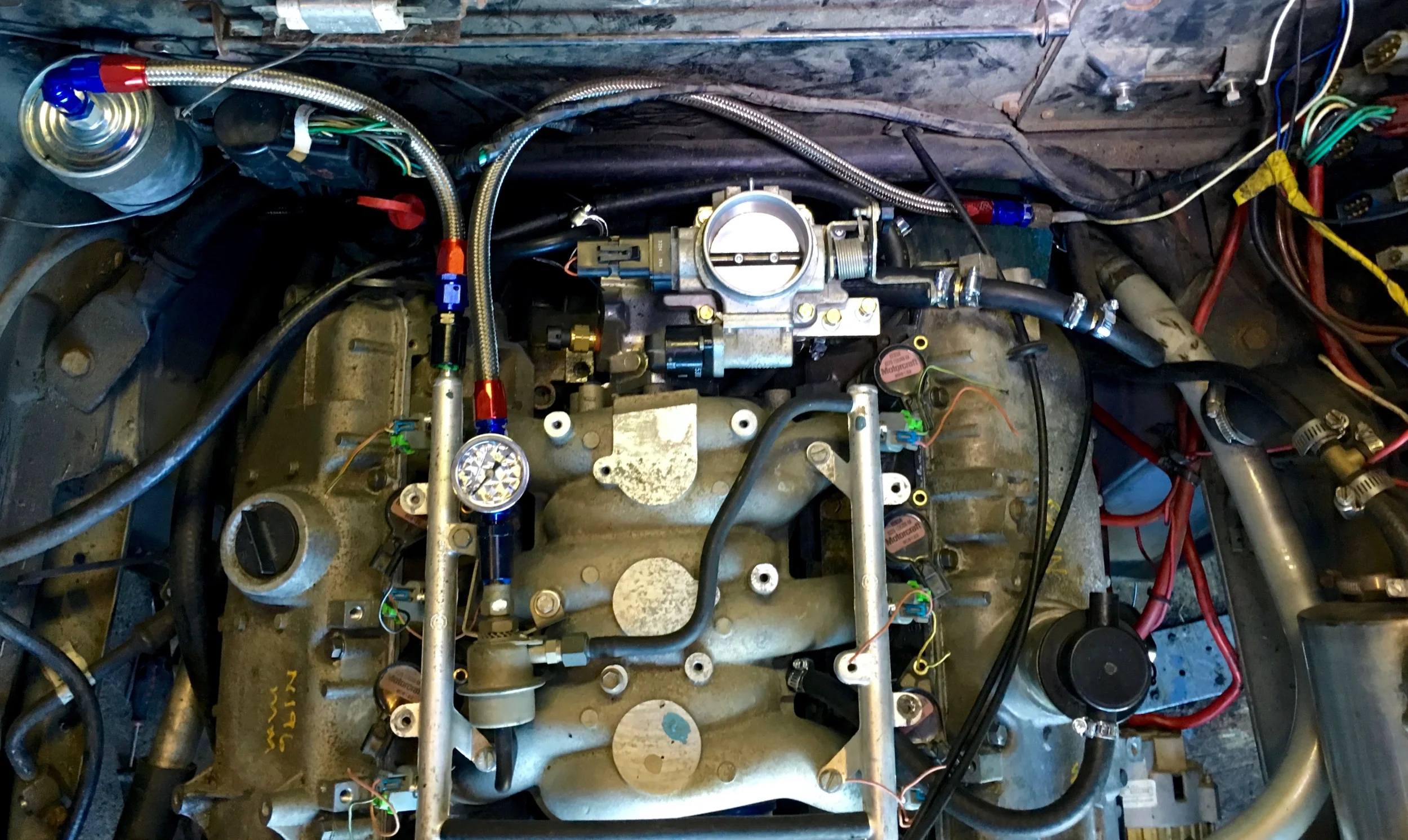
Final vacuum routing. The green line goes to MegaSquirt, the red to the vacuum reservoir and transmission, and the blue to the brake booster.
Other Vacuum Connections
There are two other vacuum lines connected to the intake manifold:
Fuel Pressure Regulator. This connects to a small nipple on the manifold when using the regulator that came with the engine. If you're using another regulator, you should cap this so that you don't have a vacuum leak.
Oil/Air Separator. This looks like the oil filler on the 2.8L engine, but is mounted on the driver side 3.0L valve cover, and is used to remove gases from the engine, routing them back into the . A small hose runs from the separator to a nipple on the intake manifold. The other end runs to the air box, according to the 3.0L manual, but since my air box is in the driver side pontoon I have to decide if I'm going to leave it open to the engine bay or run an unsightly hose into the pontoon.
Fuel Vent Line
Without the charcoal canister to collect the fumes from the fuel tank vent line, I basically have an open line to the gas tank sitting in the engine compartment. This line is important, as it allows the pressure in the tank to equalize as the fuel is pumped out. You can't seal this off; doing so would cause the tank would start to fill with vacuum as the fuel is pumped out, and it would eventually be unable to overcome the negative pressure and be unable to move any more fuel.
Normally these fumes would exit the line to be stored in the charcoal canister while the engine is off, being later routed to the intake manifold to be burned when the engine is warmed up, but until I get the engine working I'm going to skip this EVAP system altogether. I did want to keep any debris from falling into the line, though. While it is unlikely it would make it all the way to the tank, it could clog up the line itself and cause other problems.
I did pretty much what Josh did, and used a simple filter to cover the end of the line. I found a marine filter for a few bucks that would do the job, in this case an Attwood Corporation 1607-3 Black Straight Fuel Tank Vent from Amazon. The exact filter make and model doesn't matter. I doesn't do anything to keep the funds from escaping; it just keeps degree from getting in. Obviously venting fumes into the air isn't great, but it'll do until the engine is up and running and I can figure out a proper EVAP system.
The vent fits into a 5/8" inner diameter hose. The 5/8" hose also fits right over the original fuel vent line, although I don't know what size that is. After fitting the filter into the 5/8" hose, I cut the original vent hose and slid the 5/8" line over it, using a hose clamp to keep the two tightly together.
At the moment the filter assembly is just resting in the engine bay, and will probably bang against the fiberglass body. I might just zip-tie it against the rear stabilizer bar. Or takes advantage of the threads on the filter to screw it into a new hole that I'd make in the fiberglass near where the charcoal canister used to be. Or just do a proper EVAP system. I can worry about this once the engine is running.
The location of the fuel vent assembly in the engine bay, next to the relocated fuel filter.
The fuel filter installed onto a 5/8" piece of hose, which in turn was slid over the original cut vent hose and secured with a hose clamp.