Spark Plugs and Removing Old Wiring
Joe Angell
The fuel injectors were installed, so now it was time to tackle the spark plugs and MegaSquirt wiring. I had previously removed the original Champion RS9YC spark plugs, and decided to install tnewe Bosch HR6DS plugs that I'd bought for the 2.8L engine. The Bosch crossover part number is actually HDR6DC, but I couldn't find any really information on the differences, so I decided to just use these.
Spark Plugs
Before installing the injectors, they need to be gapped to 0.035", as per the Moncao/Premier Engine Manual. I managed to forget to do this for half the plugs, and had to remove them after installing them. The process is pretty easy. They sell a gapping tool at any auto parts store. It's a simple disk that gets thicker as you move around the outer edge. You simply slip it between the plug end and slid it up until it won't go any further, and you've measured the gap. It seems these injectors came gapped at 0.030", so I just needed to tilt the tool to bend the electrode out a little bit more. If you pend it too far, I found that simply pushing the electrode hard against something solid (like the floor) bends it back easily enough.
After gapping, the plugs are just dropped into the heads and torqued down with a standard 5/8" spark plug socket.. I was a bit lazy and just tightened them without a torque wrench, but you do have to be careful not to over tighten them. Similarly, if you don't tighten them enough and they pop out, you'll have misfires while you drive down the road and the car will run very poorly until you fix it.
The most annoying thing here was that there were some unused (in my setup) mounting holes on the fuel rail directly over two of the plugs. I was able to drop in the plug, then drop the socket on top of it, then drop in a socket extender and hand tighten them before attaching the wrench and torquing them down. I then had to remove the wrench, then the extender, and finally the socket with pliers.
Gapping an old spark plug to 0.035".
Coil-On-Plug, the Old Coil and the Ballast Resistor
Rather than using a single coil, I used a coil-on-plug system that Josh had set up. This works by having a separate coil for each spark plug, with the coil sitting directly on top of the plug. This eliminates spark plug wires (although now you have to run trigger wires to each coil), and ensures maximum coil power to each plug. These particular Motorcraft coils were commonly used on Fords, and are fully compatible with EDIS-6.
Josh had attached my old spark plug boots to the coils for me. He had previously detailed the coil-on-plug construction he used in a post on DMCToday.com, along with information about sourcing the parts from early a 2000 Ford Taurus and how to make them work with the 3.0L spark plug boots.
With the plugs installed, the coils simply slip onto the top. I pointed the electrical connectors towards the back and slightly to the side of the car so that I wouldn't have any trouble connecting them to the harness.
With coil-on-plug, the original coil can be be removed. It's just bolted next to the bulkhead connectors, and comes of easily by removing the two bolts with an 8mm socket. The wires on top come off with another turn of the wrench.
The ballast resistor can also be taken out, since MegaSquirt can handle its function directly (a hotter spark when starting the car). The three wires pul off easily from the spade connections on the resistor. Unfortunately for me, one of the bolts that olds mine in place was stripped, so I left it for the time being.
The coil-on-plugs installed in the car.
Cabin Wiring
The bulk of the wiring in the cabin sits under a panel in the parcel shelf behind the passenger seat that is commonly referred to as the relay compartment. I removed the carpet first, and then the back piece under the rear window via the four philips screws holding the hooks and the shelf itself in place. With the back piece out of the way, you can easily get to holes in the bulkhead to run wiring between the engine compartment and the cabin, as well as the ground and positive posts.
Before you do anything else, I'd highly recommend removing the passenger seat. You have to get under the car to access the four nuts that hold it in place. After that, you can just lift the seat out. If you can't do this, then pushing the seat as far forward as possible will make things a lot easier, but removing the seat entirely is really the best way to go. The driver's seat can stay, as it's not in the way nearly as much as the passenger seat is.
Various after market modifications I removed from the car. I may reinstall some of these after the EFI system is working.
Cleaning Up the Relay Compartment
My car had a number of aftermarket electrical additions. Some of it wasn't working, or wasn't overly practical, so I decided to pull out anything that made sense:
- Cruise control. Hasn't worked for a while, although in part that's due to every angle drive I put in binding almost immediately. I'll come up with another cruise control solution sometime later. I removed the harness and electronics box, but left the control stick and its wiring hooked up for future use.
- Remote starter. I got this from DMC NW, but the car is so loud that it's not very practical, so it's gone too.
- CounterACT anti-rust device. Commonly used in high-rust environments (such as salt mines), mine was missing a pad and wasn't completely operational. To be honest, I'm not totally sure it was doing much in the first place, as I had nothing to compare against.
Other modifications that I kept intact:
- Lockzilla replacement door lock module.
- DMC NW keyless entry system.
- Compass/temperature rear view mirror wiring.
- Heated seat wiring.
- Ignition switched headlight modification.
- Blindspot cameras and monitors.
Some of of these mods were wired into a second fusebox and relay setup that I put under the parcel shelf behind the driver's seat, so they were easy to isolate.
With those out of the way, I was added a bus bar for accessory-switched components. I had a lot of things connected to that relay, and it was a bit of a mess to deal with. Moving them to a bus bar cleaned up the compartment and simplified future maintenance. Every wire was labeled with my label printer so that I could keep track of what is what.
Lifting the Relay Compartment Tray
While messing around with my wiring, I decided it would be a good idea to move the entire metal tray that the relays and fuses are mounted in. It is held down by only two bolts, one near the front by the fuse box and the other near the back edge. The hardest part is getting to them, since there will invariably be a large bundle of wires in the way. With the tray loose you'll have an easier time getting to some of the wiring because you can move the tray relative to, lifting it up to look underneath or just get some slack on the wires. You won't be able to remove the tray, as all the components are still attached and connected to their wires.
Removing the Old ECUs
Located under a parcel shelf panel behind the passenger seat are the various engine control computers, all of which are made redundant by the EFI system. I found three: the black idle speed ECU, the silver lambda ECU, and the grey ignition ECU.
The easiest way to get all of this stuff out is to unplug the electrical connectors, unbolt the tray, and remove them all at once. I tried to take them out one at a time, but removing the whole tray first is easier.
The black idle speed ECU comes out pretty easily. There are two electrical connectors on the back that pull right out, and two philips screws that hold it in place. There is ground wire attached to one of these screws as well.
The silver lambda ECU is mounted vertically forwards of the idle ECU. The large black rubber thing with the blue wire and taped harness going into it is itself a connecter, and can be lifted upward to unplug it from the ECU. With that out of the way, you can remove the entire metal tray that the ECUs sit in via the four bolts and an 8mm socket.
Be careful lifting the tray, as the grey ignition ECU is still attached to the underside. After unplugging its cable, you can safely pull the entire tray out of the car. The Bosch box is held in with four philips screws from the top. The silver lambda ECU is held in by two screws-and-nuts that are removed by unscrewing the screws while holding the nuts with a wrench.
I also pulled the distributor wire and oxygen sensor wire through the firewall and into the cabin, since they would be either unused or replaced with new wiring. Both wires are blue. The distributor wire goes into the engine compartment and is pretty easy to spot. The oxygen sensor wire goes under the car, and is more difficult to locate without actually getting under the car yourself. In both cases you pull the grommet into the cabin and then pulling the rest of the wire and the connector in behind it.
Unscrewing the black idle speed ECU from the behind the driver's seat. The wooden shelf near the bottom of the picture is my own aftermarket modifications.
The large back rubber piece with the blue and black taped wires going into it is the connector for the lambda ECU. The 10mm wrench will be used later to remove the ECU from the tray, but only when the entire tray is out of the car.
All three ECUs removed from the car: lambda (left, silver), ignition (center, grey) and idle (right, black).
Removing the Old ECU Harnesses
This one is a bit trickier. First we'll cover the easy stuff.
Distributor Wire and Oxygen Sensor wire
There is a blue wire that runs from the distributor the ignition ECU. This goes through the bulkhead and ends in a two-prong connector that would normally connected to the distributor. I pulled it back through the bulkhead by popping the rubber grommet out and pulling the cable into the cabin.
There is another blue wire mounted lower down in the cabin that runs to the large black connector on the top of the lambda ECU. This goes to the oxygen sensor, which presumably is already unplugged. If you want to see where the wire goes, you'll have to get under the car, as it drops down below the engine bay. Again, just pull the grommet out and pull it and the cable back into the cabin.
The blue wires runs from the ignition ECU to the distributor, and from the lambda ECU to the oxygen sensor, via grommets through the body.
The oxygen sensor connector exits under the car near the driver's side engine cradle.
Wires to Bulkhead Connector and Relays
Dealing with the wires running from the ECU connectors to the harness is tougher. It eventually became clear that the best course is to remove the wires one at a time. These wires run under the center armrest and through the relay compartment, with some going to relays while others go to the bulkhead connectors. A few wires also run towards the front of the car. Most of the wiring is wrapped in black electrical tape (or self fusing silicone tape, which appears to be commonly used for harness)
Removing the Center Armrest
You need to take out the center arm rest to get to all of the harness. I created another post dedicated to that process.
Exposing the Wires in the Wrap
To remove the wire wrapping, I carefully sliced through it with a sharp utility knife. The wire insulation wound up being pretty durable, so I only cut the wrap, not the wires themselves. After a cut down the length of the wrap, I was generally able to unfold it from around the wire and remove it without too much trouble.
The main harness in the relay compartment after unwrapping.
Popping Out the Bulkhead Connectors
The bulkhead connectors need to be pulled in order to get to the wires connected to them. There are five (5) bolts that hold the bulkhead connector plate to the fiberglass body, and they can be removed with an 8mm socket. You'll then be able to move the plate a bit, but not far enough to get behind it to remove the positive wire.
Inside the car, the ground wire behind the back of the parcel shelf needs to be taken off with a 10mm wrench can on the nute. Back in the engine compartment, I then had to back off the bolt that nut was attached to so that I could shift the plate far enough to clear the hole in the firewall and expose the space behind the bulkhead connectors.
The bulkhead connectors themselves are clipped into the plate with three tabs per connector: one on the top, and one on each side near the bottom. The top one and at least one of the side ones have to be pushed in with a flathead screwdriver to pop them out through the back of the plate. The smallest connector only has two clips, one on each side.
With the connectors popped out, I could pull the plat forward a bit more sot hat I could remove the positive wire from the back of the plate. I used a 14mm wrench to hold the inner nut while I rotated the outer nut with 14mm socket. You may be able to do this from inside the car, but I found it easier to do from outside. Once everything is disconnected, you can go back in the car and pull all the wiring forward. I left the plate in the engine compartment, as it was still connected to the ground and positive wires that run to the rest of the engine compartment.
A note on bulkhead connector colors: According to the bulkhead connector guide I found on DMCTalk.org, the first row of connectors should be Yellow, Red, Blue, and the second row should be White (7 pins), Black, and White (9 pins), plus the small White (three pins) connector between the two rows on the right . As you can see, mine were not set up this way, as the right side White (9 pins) and Blue ones were swapped. It doesn't really matter, as long as you plug in everything correctly. Also, the Yellow connector was actually white, but had a very faded and easy to miss yellow dot sticker on it. You don't have to worry about confusing the White connectors with each other when reinstalling because they each have a different number of pins, although you can just check the wiring colors against the bulkhead connector guide when reinstalling them to be sure. Of course, I'll be replacing the wiring on a White, Blue and Yellow connectors anyway, but matching up the colors will still work.
A 10mm socket removes the 5 nuts holding the connector plate onto the fiberglass body.
Inside the car, the ground wire can be removed with an 8mm socket.
The top and one of the side tabs on each bulkhead connector have to be pushed out to drop the connector through the back of the plate.
The positive wire can be removed from the back of the plate with two 14mm wrenches.
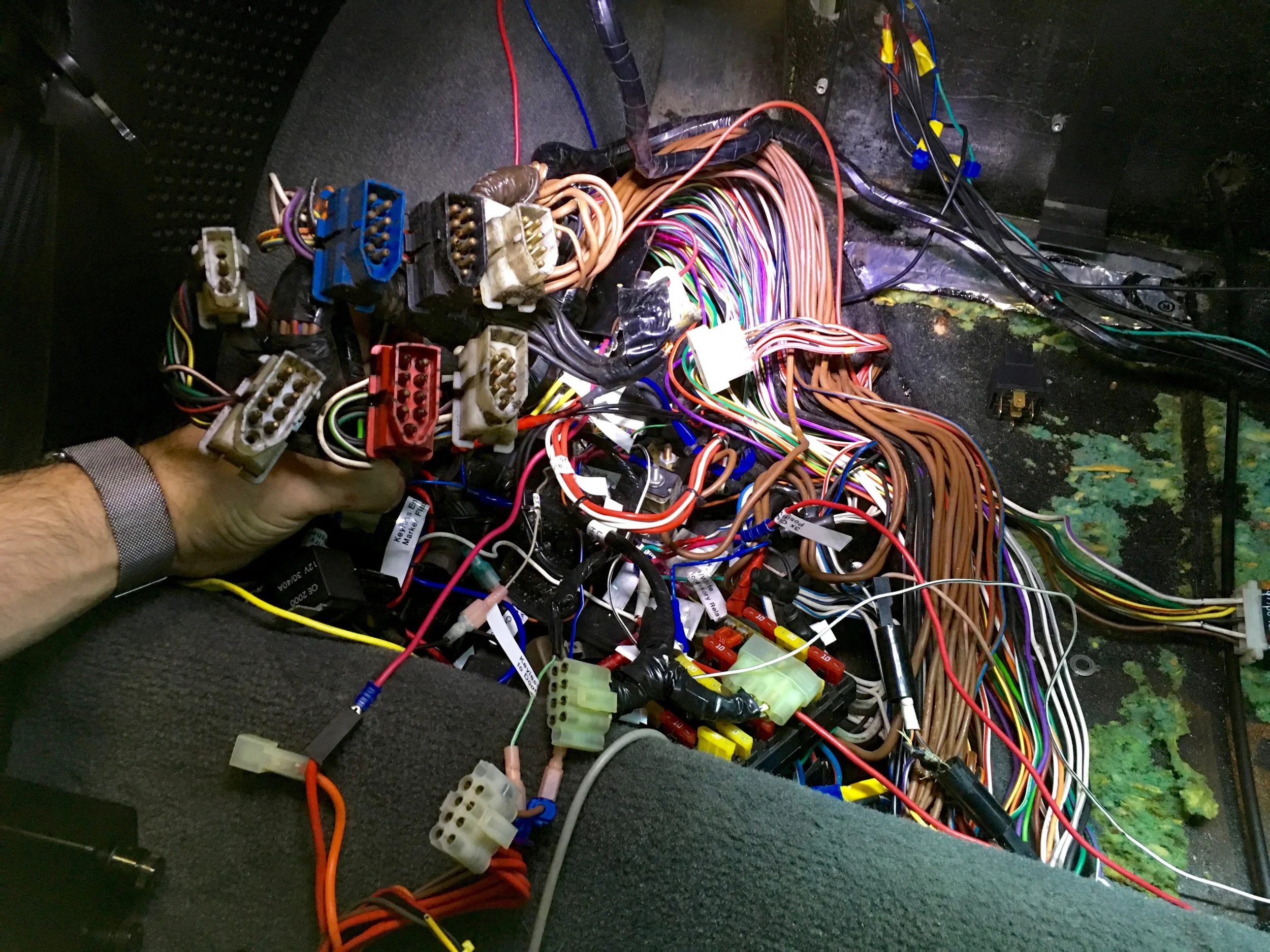
The bundle of liberated bulkhead connectors and unwrapped wiring harness in the relay compartment
Removing Old ECU and Bulkhead Connector Wires
There are a lot of wires we no longer need, so we can pull them out of the car. This isn't actually very hard. I looked at were the wires entered the armrest area from behind the driver's seat, and tugged on them one at a time, tracing them through the relay compartment to their final location in the engine bay. Many of them went right to a bulkhead connector, making it easy to make sure I wasn't cutting something I wasn't supposed to.
The pins are a real pain to get out of the connectors, so I opted to cut the wires a few inches from the connector instead. I then pull the wire out through the compartment and tossed it to the side.
Some of the other pins went to less obvious locations. Wiring diagrams help a lot here, such as this colored one available from DMCTalk.org. For example, one wire goes to the fuel fuel pump relay. There's also a red/brown wire that runs through the bulkhead to the to the frequency value via the smallest bulkhead connector, then runs back into the relay compartment through that same connector and to the main fuel relay via the red/purple wire. There is no longer a frequency value, so all that wiring can go to. The fuel relay will be reused by the MegaSquirt installation (according to Josh's diagram), but with new wiring.
I did manage to cut the wrong wire once. A white/slate wire runs into a bundle of identically colored wires in the relay compartment, and I mistakenly cut the wrong one. Luckily, I left enough slack that I could install a butt connector without much trouble. After that I was more careful with which wires I cut.
I also cut a few wires that I thought went to the ECUs, but actually went to things like the parking brake via the same hole through the parcel shelf. Again I had been careful enough to leave a few inches on the wires before cutting them so that I could add bugs connectors back in.
By the time I was done, I had completely removed the Blue, White (9 pin) and White (3 pin) bulkhead connectors, and removed a few wires from the Black and Yellow connectors as well.
The List
The following wires went directly from the ECUs to the bulkhead connectors:
- White/Slate (x2)
- Green/Yellow
- Black (x2)
- Light Green
- Orange
- Red/Brown
- Black/Yellow
- Black/Green
- Black/Light Green
- Black/Pink
- Black/Slate
- Black/Red
Some of the wires were a bit more involved:
- The wiring for the cold start valve and starter motor solenoid. This is a Black/Blue wire that runs from the White (9 pin) connector to the hot start relay, then to the White (3 pin) connector. The other pin on the White (3 pin) connector (only two of the three pins are used) has a White/Red wire that leads to starter motor. Obviously we'll eventually need to run the starter, but not with the way the wiring was originally configured. A second White/Red wire runs from the from same White (3 pin) connector pin to the start inhibit relay, which we'll also be reusing later to make sure the car can only be started when in Park or Neutral.
- A Red/Purple wire running from the White (7 pin) connector to main fuel relay. I cut the wire at the connector and left the long tail running to the relay, as we'll be reusing that later as well.
- Two (2) Green wires from ECUs to green bundle in center armrest. You'll have to cut the harness wrap to pull these out. Another Green wire runs from the bundle to the White (9 pin) connector.
- Four (4) Black wires run from the ECUs to the Black bundle in center armrest.
Also, you should be aware of the following:
- Two wires, one Black and one Black/Purple, see to group to the ECU harness, but actually go down the side of the armrest to the driver's side seatbelt, and are used to turn on the "fasten seatbelt" light on the instrument cluster.
- Two more wires, one Black and one Black/White, go through the parcel shelf wall with the ECU harness, cut are not part of the harness. They instead run to the parking brake to run the "parking brake on" light on the instrument cluster.
Other Wires that can be removed, as they are no longer needed.
- A Blue/Yellow from the Yellow connector to Blue connector, both of which run to the ballast resistor on the other side of the harness. MegaSquirt will be controlling spark and doesn't need that to do its job.
- A Yellow/Red wire from Blue connector to warm up regulator via the RPM Relay. Neither the RPM relay nor the warm up regulator are used with MegaSquirt, as it controls the fuel pump directly.
- A Purple wire from the Blue connector to Center Armrest Bundle, which is used for diagnostics.
- A White wire from the Blue connector to a bundle of white wires located just behind the fuse box.
Location of the black, green and purple bundles in the center armrest.
All of the wiring I puled from the car, including the White (9 pin), White (3 pin) and Blue bulkhead connectors, plus the ECU harnesses.
Consolidating the Bulkhead Connectors
One major issue I had with Josh's wiring harness was that he had a manual transmission, but I had an automatic. This was an issue because Josh had used the red, white and blue bulkhead connectors for MegaSquirt duties, but the red is used for the transmission on the automatic. This meant that I needed to move the wires from the red connector to the other connectors.
Luckily, there were exactly the right number of pins free on the other connectors, so in principle this was easy. It turns out it's a real pain to remove the pins and sockets from the connectors, though. I bought a Lisle 57750 wire terminal toolkit from Amazon which contains blue, red and silver tools, but unfortunately none of them fit the connectors. I next went to BritishWiring.com and bought their two wire removal tool set, one green and one purple, as well as two 9 pin connectors with pins and sockets so that if worst came to worst I could just cut the wires. The connectors only come in white, but I just needed the pins and sockets so that I could install the wires from the red connector into the blue and white connector housings.
One of the cylindrical ends of one of the BritishWiring.com tools fit around the connector pins, and with enough pressure I was able to pop most of them out. The sockets were another story -- I finally gave up and simply cut the wires, stripped them, attached them to new sockets with a proper open barrel crimp tool (you really want the right tool for this; it's the same one you use for the fuse box), and popped them into the empty holes in the blue and white connectors as needed.
Wasted Effort
Turns out I didn't need to do any of that. Had a paid closer attention to Josh's diagram, I would have noticed that the Yellow connector comes out as well. The faded yellow sticker on the otherwise white connector made it harder to keep track of which was which, so I got them a bit confused. The point is, I could have just plugged the second Red connector in where the White connector used to be and been done with it. No harm done, though, since both have to come out anyway; I just wasted time and money, but did no damage.
Removing Yellow Connector Wiring
The remaining wires on the yellow connector were taken out as well:
- Blue/Yellow. Goes to the ignition bypass resistor, which isn't used with MegaSquirt.
- Black/Orange. This goes to from the Otterstat to the fan fail relay by way of a diode to turn on the fans when the engine gets too hot. This will accomplished directly by MegaSquirt.
- Green. Goes to the the Otterstat.
- Purple/White. This one goes to the engine bay light, so you may want to retain it. I don't think I've ever seen that lit in my car, so I just removed it.
- Black. This wasn't in the bulkhead connector diagram, and ran to a bundle of black wires in the relay compartment. Presumably a ground of some sort.
The other pins have no wires in them.
The otterstat (Black/Orange and Green wires) isn't used with MegaSquirt, as it controls the fan directly from engine temperature rather than relaying on a simple temperature switch. I left the otterstat in place, since it's plugging what would otherwise be a hole in the coolant pipe, but it isn't hooked up to anything.
Removing Relays and Related Wiring
Next was to remove some now-unused relays.
The RPM relay (35) controls the fuel flow, among other things (it's more of a little computer than a relay, really). Two of these wires are retained for MegaSquirt:
- White/Slate. This is a tachometer pulse wire that goes to a bundle of white/slate wires, and from there to the coil negative, idle speed relay, ignition control unit (which actually provides the pulse), and the tachometer. With the EFI conversion, everything but the tachometer itself is removed, with MegaSquirt itself providing the pulse to drive it.
- White/Purple. This is used by the RPM relay to turn on the fuel pump, and will be reused by the MegaSquirt installation.
The remaining wires are removed:
- Brown. This is an always-live power wire to the RPM relay, running through fuse 7.
- Yellow/Red. This goes to the Lambda relay, and through the Blue bulkhead connector to the now-removed warm up regulator.
- Green. Runs from fuse 1, and is hot when the ignition is in the Start or Run position. I retained the wire in case I could use it in the future.
- Black. Runs to ground, chaining to the other relays. Again I retained the wire in case I wanted to hook it up to something else.
The fan fail relay (27) and fan relay (26) are removed entirely along with the circuit breaker (20), although the black/green the wires to the fans controlled by MegaSquirt. The blue fan fail "relay" is is more of a module than a relay, with non-standard relay wiring and both provides power to the fans and turns on a "fail" light on the dash when they stop working. Due to its tendency to itself melt and fail, most owners have already replaced it with a jumper as per service bulletin ST-06-9/82.
You can keep the breaker if you want, but I didn't. The breaker serves to cut off power to the fans if they get stuck or otherwise start drawing too much power. I'm not overly concerned about this happening, and I have a low-power, high-performance Wings-B-Cool kit from DeLorean Parts Northwest installed anyway. Howver, a stalled (seized and unable to spin) motor can draw a large amount of power, damaging wiring and risking fire due to the heat generated. For these reason I've kept the the breaker in case I decide to install it on the line to the new fan relay I'll be adding in the future.
- Black/Green. Two separate wires coming out of two pines on the relay, one for each fan. Retain for wiring to MegaSquirt.
- Brown/Orange (Heavy), Breaker, and Brown/Orange (Heavy). The Brown/Orange wire goes from the fan fail relay through the breaker, and then back to the fan relay as the brown/Orange wire. These are as large as they are due to the amount of power they carry for both of the original fans. Both are removed.
- Black/Orange (Thinner) from Otterstat and A/C Compressor. This wire turns on the fans. The wire splits to connect to the Otterstat (by way of the Yellow bulkhead connector) and the A/C compressor (pink wire), each with a diode. The diode ensures that the "fans on" signal from either one of them doesn't feed into the other one. The entire wire and the Otterstat diode can be removed completely, as in the EFI conversion a relay will be used to control the fans from Megasquirt. The pink wire from the A/C compressor and its diode should be retained; it's purpose is to turn on the fans when the compressor is on, which is not something MegaSquirt controls.
- Black. This goes to ground, and is connected to the other relays in a chain. I simply unplugged it from the relay socket for later use.
- Brown (Very Heavy). This is the main power to the relays, and comes directly from the battery. I retained the wire for other uses.`
The A/C compressor diode, Otterstat diode, and related wiring that turns on the cooling fans in a stock installation.
The fan circuit breaker and the heavy Brown/Orange and Brown/Black wires that feed it.
The Lambda relay (31) is also unnecessary, since there's no Lambda system anymore.
- Black: Ground. I removed the pin from the socket and retained the wire.
- Brown: There are two wires here, both connected to the same pin. One runs from the battery positive (always live) through fuse 7, and the other to the RPM relay.. I removed the former from the socket and retained it in case I needed it in the future, and completely removed the latter.
- Yellow/Red. This goes to the RPM relay and is removed.
- Green/Yellow. This goes to the previously-removed Lambda ECU, and is removed
- Red/Purple. This goes to the previously-removed frequency valve, and is also removed.
I had also previously installed LED door lights in my car. The white light delay module (25) doesn't work with LEDs, and just causes them to stay on all the time. The fix for that is to simply remove the module, which causes the lights to simply turn off immediately when the doors are closed, but still turn on when they are opened. While I was removing other wiring, I thought I'd remove the whole socket.
I don't know how the internals of the delay module work, but the wiring is very simple. There is a short purple/white jumper between two terminals, and two longer purple/white wires that run between the lights and power. I Simply cut the two longer wires off, slid on some heat-shrink tubing, and soldered them together (or you could crimp on blade connectors, if you prefer). The socket can then be removed entirely.
I had now removed four relays from my car, plus for some reason I had an empty socket at the end of the front row. This meant that I had a total of five empty relay sockets, and I have five new relays that I need to install. Perfect.