Modern Bulkhead Connector
Joe Angell
After exhausting everything else that was keeping my car from starting, I decided to trace all of the EFI wiring from the MegaSquirt and EDIS through the bulkhead and to the engine components. I took this opportunity to replace the four original-style bulkhead connectors with a a single new, modern 31-pin design, complete with a new plastic bulkhead plate.
Rationale
The original bulkhead connectors worked fine back in the day, but they are really hard to find suitable replacement parts for. I had to replace some pins with ones from BritishWiring.com, but the pins and connectors are a little different, aren’t completely interchangeable with the original connectors, and they didn’t have female connectors designed to mount in bulkheads.
Since I was tracing the wiring anyway, this was a good time to replace them with something more robust and easier to work on.
I did this work with no intention of putting the coil cover back on, since it never really fit anyway. I also no longer have a single coil, as my EFI setup can use either coil-on-plug or coil packs, and thus didn’t have to accommodate mounting one.
Which Connectors?
I only replaced the bulkhead connectors used for EFI. I left the red automatic transmission connector and the black taillight connector as-is. These are independent of the rest of the harnesses, and I want to be able remove them separately (ie: taking out the black connector harness with the rear fascia). In the future I may replace them, but for now they’re fine.
For EFI, I went with a Deutsch HDP20 31-pin bulkhead connector kit, which I got from Amazon This is a weatherproof design intended for trucks and other vehicles, and supports 14-16 gauge wire. Some of the EFI wires are thinner than that, and using those thinner wires compromises the waterproofing a bit, but since the original DeLorean connectors were certainly not watertight and still worked fine, I wasn’t concerned about it.
The HDP20 is a pretty nice design. You line up the male and female sides, push them together, then twist it until it locks. The connector ring rotates and pulls the two halves together, creating a firm, tight connection.
To install the wires, you crimp them into their pins (I also soldered the wires in place, which was especially useful for the smaller gauge ones) and simply push them into through the rubbery back of the connector until they click. You have to be careful not to use too much solder or too big gauge of wires (don't try to put two 14 gauge wires on a pin) or else it won’t fit and won’t sit all the way in the connector.
Removing pins isn’t very hard. It comes with a simple plastic tool that you slide in the back of the connector, pushing it in as far as you can. I also twisted it to make sure I released the pin, then pulled on the wire to remove the pin from the connector. If the pin wasn’t loose, it usually just meant I hadn’t pushed the tool in far enough yet.
Both halves of the connector, stamped pins, green removal tool, and white plugs.
A. better look at the connectors. The blue/orange parts are the outside, where the wires go in.
Inside the connectors. Each pin is labeled.
The coupled connector. The notched ring turns to lock the two pieces together. The nut and washer are used to lock the other end against the bulkhead.
How a pin is inserted into the connector from the back, by simply pushing it through the silicone barrier.
I only needed about 27 pins of the 31 pin connector, which meant that I had some spare pins for when I inevitably messed something up. It also includes a half dozen plugs to use in place of pins for the extra holes in the connector. These help maintain the weatherproofed integrity of the connector itself, and are easy to remove if you decide to insert pins later.
Removing the Old Connectors
Before you begin, disconnect the battery. I forgot to do this and got some nice sparks when I accidentally shorted the main positive wire to to the main ground stud.
Next unplug the plugs from bulkhead connectors to make some room. If you have the original coil remove its two (2) bolts with a 13 mm socket.
The bulkhead plate is held in with six (6) bolts that are removed with an 8mm wrench, or socket if you can fit one in. You also have to remove the ground stud and the main positive stud, which run through the plate. These use 10mm wrenches, but you’ll need two (or a wrench and a socket).
The ground stud goes through the fiberglass body, so you’ll have to use two wrenches while reaching around from the engine bay to interior to break the nut free. The positive stud only goes through the bulkhead plate, which should now be loose and can be moved away from the body to insert a wrench.
The bulkhead connectors themselves are held in by three tabs: one on the top, and two on each side. One released, you can push the connector backwards through the plate. I found it easiest to pop the top one first, then tilt the connector back while releasing the side ones.
With the connectors free, you can now remove the plate.
Transferring the Wires
Moving to the new connector is fairly straight forward. You cut the old wire close to the original connector, strip it, crimp it into the appropriate pin, and insert it into the back of the appropriate half of the new connector. Make sure you use the right pins and put the right connector on the outside of the car — the connector with the female pins is mounted to the bulkhead, and has the wires that run from the cabin. The male pins are for the wires in the engine bay, and is the connector with the rotating ring.
You need a special but common crimp tool to properly crimp the wires properly. This is the “A03BC” standard for uninsulated tabs, which looks like a “w” or “m” shape. This is the same tool used for the fuse box, if you’ve replaced that.
The wire should be placed so that the insulation is grabbed by the outer tabs, while the wire is grabbed by the inner tabs. This ensures a good electrical connection and that the insulation can act as a strain relief.
When inserting the pin into the tool, make sure you only crimp the part of the pin that has the tabs that need to be bent in. Be very careful not to crimp the ring near between the round part of the pin and the tabs, as this ring is how it locks into the connector. If you crush that, you either won’t be able to get the pin all the way into the connector, or you won’t be able to get it to lock. I ruined two pins before I figured that out.
After crimping, I carefully applied solder to the wire and pin. Don’t use too much solder, or the pin won’t fit in the connector.
At this point I used a multimeter in continuity mode to make sure I actually had a solid connection from all the way along the wire. Once I was sure of that, I slid the pin through the rubbery back of the connector until it clicked. The rubber is intentionally tight to provide a weather seal. The docs note that you should not use any kind of heat shrink, as this will affect the weather seal and seating of the pin.
Now just repeat for the other side of the wire/connector until you’re done.
I wound up making a few more changes while I was here. Some of the wires were a little short, so I used some 16 or 14 gauge wire to lengthen them, soldering a few inches to the end of the original wire and covering the joint with heat shrink before attaching the pin. Unfortunately, I only had red wire for much of this, but it’s simple to find the properly colored wires at the end of those extensions.
Incorrectly crimped connector on the left. Notice that the ring (which secures the pin inside the socket) at the base of the pin is crushed, while in the middle it is not. The rightmost pin hasn’t been crimped yet.
A properly crimped connector. The ring is not damaged, the bare wire is crimped by the topmost tabs, and the insulation is gripped by the bottommost tabs.
Making a New Bulkhead Plate
This new bulkhead connector obviously won’t fit in the existing bulkhead plate. I had two options: mangle the original plate, or build a new one.
I had some leftover 1/4” ABS plastic that I’d previously bought from Amazon for some of my radio mounting experiments, so I decided to build a new plate. The piece I had was 12” x 12”, which was perfect.
Somewhat annoyingly, there are only two screws on the bulkhead connector side of the plate, and four on the coil side. This meant I needed to bend my ABS plastic sheet. This wasn’t actually as much of a problem as I expected.
Bending the Plate
I started by placing the original plate on my piece of plastic and tracing a line wit ha silver Sharpie where the plate bent. Surprisingly, this was not a straight 90 degree bend, but on a bit of an angle, so it’s a good thing I marked it this way.
I then clamped the ABS sheet between a 2x4 and my workbench, lining up the 2x4 with the marked line. To bend it, I simply used a heat gun to soften the plastic, moving it back and forth along the line, while pulling upward with my free hand. After about a minute, it started to bend. I kept going, slowly curling it upward until it was vertical. Once it cooled off, it was bent just how I needed it.
Bending the 1/4” ABS plastic with a heat gun to match the original bend of the metal bulkhead plate.
Cutting the Holes
I wound need to cut a few holes in my new plate:
31-pin connector hole
Automatic transmission rectangular hole
Taillight rectangular hole
Ground post hole
Positive post hole
Other wires hole
Four screw holes
I began with the 31-pin connector hole. I wound up having to do this twice, as I didn’t measure properly and drilled it too low the first time. I made. crude circle by tracing the plug as best I could onto the plastic. This would have been a lot easier if I’d done it when it didn’t have all the pins installed, but it was too late for that now.
The connector body has a “D” shape so that once it’s mounted it won’t turn in the hole. The catch is how to make a “D” shaped hole. The flat side is pretty small, and requires a lot of precision to cut correctly. There are sell special cutting dies that cost a couple hundred bucks that can stamp the shape out through plastic or metal, but that’s a silly expense for a single use.
I went with drilling a tight hole and simply ignoring the “D” part. Another option, is to buy a hole saw that’s a tiny bit too small, but I did it a bit more free-form. I started with a power drill to make the initial hole in about the right place. I then used a Dremel with a conical sanding bit to widen the hole. The bit melts the plastic, allowing you to knock it out of the way with your fingers as it comes loose. Just don’t let this plastic cool while still attached, or you’ll have to grind it back off again. I periodically tested the connector in the hole, making it a little bigger each time until it was a very, very tight fit, popping over the screw threads and sitting firmly against the plastic base.
I followed the same procedure for the rectangular holes, tracing the shape from the original metal plate. I put one above the 31 pin connector and one to the side. The Dremel can’t really do square holes, but I got it close enough. Unfortunately, the 1/4” thick plastic is too thick for the connector clips, but I was able to get them to fit very tightly. The black connector is quite tight and stays in almost by friction, while the red one is fairly tight and mostly stays in place. If they come loose, I may add a couple of screws through the front with washers and nuts on the back to keep the connector from falling backwards.
The ground post, positive post and other wires hole were again marked from the metal plate, then drilled and widened with the Dremel as needed.
The screw holes were also marked from the metal plate, although I only needed the two on the side wall and two of the four on the back wall, since my piece of plastic wasn’t as wide as the original plate. These were then drilled and cut into slots with the Dremel. It took a few test fits to get the size of the slots right.
Installation
I mounted the 31 pin connector first, since that was the hardest one. After forcing it through the just-big-enough hole I’d made, I put on the wavy washer and the plastic nut and tightened it as much as I could by hand. I then grabbed the wire side of the connector and used an adjustable wrench to turn the note a few more times until the washer was basically flat, being careful to ensure that the flat part of the connector was upward (I also marked “up” with a silver sharpie on both connectors). Once tight, it didn’t rotate when I connected the male side of the connector and locked it.
The rectangular connectors fit through the back and hold in with friction, since the tabs can’t catch on the 1/4” thick plastic. It’s good enough, and I don’t think they’ll fall through. The hardest part is holding them while plugging in the male cables, especially the red one, as I made that hole a tiny bit too large.
As an extra detail I lined the perimeter of the back of the plate with air conditioner insulation tape. This helps seal it a bit better and keeps some noise and weather out.
At this point I could secure the plate to the firewall with four of the six original bolts. However, those original bolts wound up being a touch too short to reach through the weather stripping, and I wound up ordering some longer M5 stainless steel bolts. These worked perfectly, and compressed the weather stripping to seal the panel to the bulkhead.
The ground and positive posts just bolt through the same way they did in the original plate, although I don’t need the plastic isolator that was originally used to keep the positive post from grounding out on the old metal plate. I replaced the posts with new stainless steel bolts, nuts and washers, as the old ones were getting stripped and corroded.
The final step was to run the other random wires (the backup sensors, mostly) through the “other wires” hole, and plug in the new round connector and the original red and black bulkhead connectors, and I was good to go.
1/4” thick weather stripping lining the perimeter of the cover to provide some sailing and sound insulation.
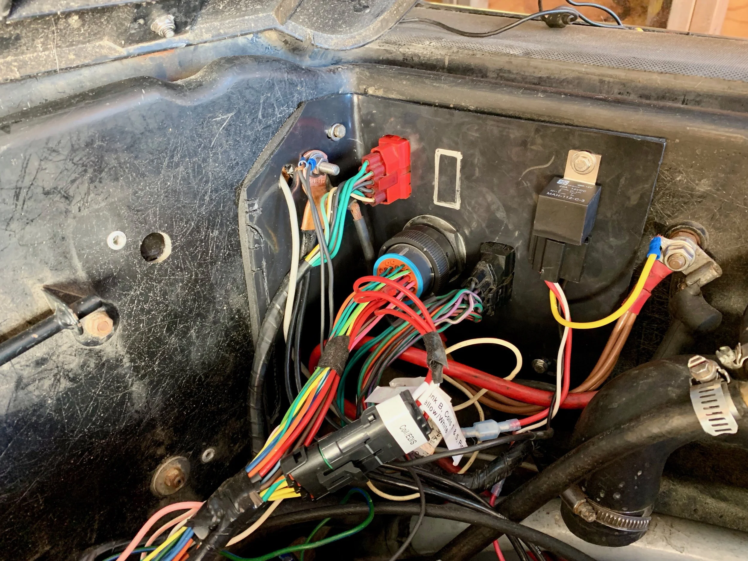
Final installation with two original connectors, the new connector, the ground and positive posts, and some other wires that run through the bulkhead. The relay is and add-on to provide direct battery power to the starter solenoid from the start inhibit relay in the cabin as an alternative to a service bulletin fix.