Ignition and Idle
Joe Angell
This is a long, rambling post composed over several months as I got the engine to start, but then I moved some wires and it wouldn’t run again. I’m keeping it because it outlines the troubleshooting processes and all the things I tried to get it working, and finally figuring out what the issue was and fixing it. Other real but unrelated problems were found as part of this process.
After a quick run to the gas station for a couple gallons of gas (and spilling some into the filler when I forgot to push open the DeLorean's spring-loaded flap with the gas can's nozzle), I finally turned try key on my EFI conversion. I cranked it for a few seconds, released the key from a few seconds, and within half a minute the car actually caught and started to idle.
To be honest, I'm surprised it worked. I expected it to give me a lot more trouble. Of course, it wasn't working correctly...
Rough Idle
While it idles, it doesn't idle well. The idle is in the 600-800 RPM range, but it's rough, and sounds more like an air compressor than a car engine, like it's misfiring. There was also what looked like white exhaust (I'm bad at reading the colors), and a strong unburned fuel smell, which implied that it was running very rich. If I gave it some gas, it wouldn't seem to get much more power (but it would rev a bit), and would soon stall out.
I had my laptop plugged into Megasquirt this entire time, and thought to turn on logging for the second test, and again after it was already running for the third test. There are so many variables that I wasn't quite sure what I was looking at, so I brought the laptop home and posted to DMCTalk to see if anyone had any ideas. I also recorded a short video, which I sent to my friend who had previously helped me work on the DeLorean if he know what was going on.
Both dn010 on DMCTalk and my friend both suggested that I might have just plugged the harness connectors into the wrong coils or injectors, which is pretty simple to test. dn010 also suggested I try simultaneous instead of alternate injector squirting, which may help fix the idle problems. Both also suggested checking the timing before I go much further; it should be close already, but it might be off by a few degrees, and that would be enough to cause problems like this.
The MAP Hose
FAMBombjoy on DMCTalk noticed that MAP reading was 101 kPa, which is roughly atmospheric. There should have been a vacuum while the car is running. It turns out I simply forgot to plug the hose from the manifold into the MAP input on the MegaSquirt box. Simply doing that fixed the MAP reading.
Now the engine cranks, but it won't catch and stay running unless I give it some gas. I was able to get it to rev when opening the throttle now that the MAP line was connected, and get it to about 700 revs steady with the gas partly down, but it made that machine-gunning sound like it did without MAP. This makes sense if the timing is still way off. The car eventually stalled out, and wouldn't start again. Time to look at the timing.
Injector Size and Initial Tables
The injectors I'm using are 22 lb/hr, but I wasn't actually sure what fuel pressure they expect to run at. Some googling found a thread suggesting that these specific Bosch injectors are rated at 43 PSI, but when used with a 40 PSI system (which is what the 3.0L's stock regulator is rated for) they're 21 lb/hr. I re-regenerated the VE table for this 21 lb/hr in TunerStudio, although I wonder how significant 1 lb/hr is here.
It's worth noting that Josh's original setup had 19 lb/hr injectors. When the original package got lost in the mail, he replaced them with some 22 lb/hr injectors that were more readily available to him. The original box did eventually arrive, so I could switch to the 19 lb/hr injectors if I so desire, but I'm sticking with the 22 lb/hr ones for now.
Most importantly, I discovered that I had incorrectly entered the engine's information into the table generators. I had set the maximum torque at 2750 RPM, but it should have been 3750. This completely changed the VE and AFR tables.
I took another look at the Spark Advance table that I had previously generated from the MicroSquirt site, comparing it to Josh's. Mine was about 2 degrees higher than his for everything below 1200 RPM. That seemed odd to me, so I exported Josh's table and loaded it into mine.
Unusual VR Sensor Mount and EDIS Timing
I took off the engine's plastic cover to check the plugs and make sure everything was connected correctly. While it's mostly standard, there are a few unusual things about Josh's setup, and therefore my setup.
EDIS-6 has three channels, labeled A, B and C. Each channel is connected to a pair of spark plugs, with one plug being on the cylinder that we actually want to fire on the compression stroke, and the other being on its opposite cylinder that is in its exhaust stroke. This second cylinder is receiving the wasted spark — nothing happens when it goes off. Since two complete crank revolutions are required to fire all of the cylinders of a four stroke engine, you'd normally need a separate cam position sensor to know when to fire the spark plugs.. With wasted spark, you can rely solely on a 36-1 missing tooth crank sensor, firing two spark plugs at a time every 120 degrees (modified by the advance), but with only one of the pair actually ignite a fuel/air mixture, while the other is “wasted” and does nothing because its piston is on the exhaust stroke. Nice and simple.
The standard EDIS channel firing order is ACB. Josh set up his wiring to use BAC order. This is just the normal ACB order rotated 120 degrees. Josh also has his missing gear welded six teeth before of TDC, which is correct for EDIS, minus another 120 degrees (12 teeth). I believe the BAC firing order is to allow for the VR sensor to be placed on the lower left of the timing cover, thereby effectively rotating the mounting 120 degrees. The other solution to this would be to just rotate the entire gear, since all EDIS wants is for the missing tooth to be read six teeth after TDC, not that the gear needs to be placed six teeth off of the pulley when the pulley is at TDC. Josh’s solution is fine as long as you know how it works.
Initial VR Sensor Alignment
Another very important detail of Josh's setup is how much adjustment range there is in the mounting bracket for the VR sensor. Each tooth of a 36-1 missing tooth gear is 5 degrees, as is each gap; therefore, from the leading edge of one tooth to the leading edge of the next, it's 10 degrees. There is at least 20 degrees of adjustment in the bracket. Even just a few degrees will be enough to make a car run badly. It's actually amazing the car runs at all, considering that my timing is completely unknown at this point.
This means that I needed to fix the timing before I got much farther. I had initially set VR sensor bracket to one extreme, so I repositioned it to the middle first, which should be closer to the correct position.
But to actually check the timing with EDIS, the car needs to be running, not simply cranking. This is because EDIS only reports a reliable signal over ~400 RPMs, according to the MegaManual; below that, it reads 0 degrees and slowly increases, which means you can't time it while just cranking. EDIS also features a limp-home mode when it loses signal from the MegaSquirt controller, which locks the ignition timing to 10 degrees of advance. Josh had included the commonly-installed removable link on the SAW/PIP wire from MegaSquirt to EDIS; removing it enables limp-home mode.
This got me back to my first step again: getting the car to idle at all, even with the bad timing.
Sensor Calibration
I started this process about four years ago. Since then, a quick-start guide has been released that provides step-by-step instructions to make sure that you actually set up everything correctly before the initial run. In my case, it's in the MegaSquirt II Setting Up Manual.
After remembering to plug in the MAP line, I scanned through the steps to find out which one matched where I was: Section 2.11, Setup Sensor Calibrations to Match Hardware. I had already calibrated the TPS (section 2.11), so I skipped that one (2.11.1), and the MAP was built into MegaSquirt, so no calibration was necessary there (2.11.2). The coolant (CLT) and manifold air temperature (MAT) sensors were already calibrated as well (2.11.4). I had also previously configured my wideband O2 sensor before I'd found this guide (2.11.5).
I then tested all the sensor calibrations (2.12). The CLT and MAT sensors were installed, so I just confirmed that they read air temperature. MAP sensor read atmospheric (~101 kPa, dropping as vacuum was introduced during cranking) and the TPS range looked good.
The battery voltage read a bit low, at 11.7v (as opposed to 12v-13v), which is roughly what the gauge on the dash read as well. I've always had some trouble with the battery readings in my car, and it was hooked up to a battery tender this entire time, so I was reasonably sure that it was properly charged. I've never been able to figure out where any drain might be coming from, so I've just decided to live with it. I had hoped that the new ground bus would fix it, but apparently it wasn't quite as effective as I'd hoped.
Verifying Initial Tune Settings
Although I had already set up the initial tune, I decoded to go through it once again, this time comparing it to the steps in the MegaSquirt quick start guide. I also switched from the cheap Core 2 Duo Windows laptop I'd bought for EFI to my now rather old 2011 MacBook Pro, which is just a lot easier to work with and has a much better trackpad.
I checked the Required Fuel first. This seemed to be quite far off -- in the mid-20s, where when I recalculated the fuel amount with the correct settings (2975 CC engine, 6 cylinders, 21 lb/hr injector flow, and 14.7 AFR) I got 15.1. I set this as my new value.
For the control algorithm (2.13.1), I continued to use Speed Density, which matches my use of MAP as the only fuel system sensor input. I could have used TPS-only, but the guide says that MAP-only is more reliable.
Everything else in the Engine and Sequential Settings panel was left as I had set it up before: 2 squirts per engine cycle, simultaneous injector staging, four stroke, 6 cylinders, 6 injectors, even fire, 2975 cc engine displacement and 221 cc injector size (converted from 21 lb/hr at 40 PSI). I didn't touch the right side, as I didn't need to do anything there. The "ms" field next to Required Fuel was the only one that I wasn't sure about; it was populated with 7.55 ms, so I just left it alone.
For the Injector Dead Time (2.13.3), I used 0.9 ms for my high-impedance injectors, which is dead middle between the recommended 0.8 and 1.0 ms. I left all other settings alone.
Next was 2.13.4, the Ignition Options/Wheel Decoder panel. I confirmed that Spark Mode was set to EDIS. As for the rest, the setup guide just said to refer to the manual for your specific MegaSquirt version, but that didn't seem to have anything specific about TunerStudio settings for EDIS. It is, however, in the Settings/Megatune part of the EDIS Ignition Control webpage, which is where I got the settings I'd previously entered into TunerStudio.
I also compared this to compare to Josh's known good tune, which is set up like this. It is set up identically to the webpage above, except that he is using Falling Edge instead of Rising Edge for the Ignition Input Capture. The webpage seems to suggest that this isn't common, but since I know Josh's configuration worked, I'm going to go with it.
In the Idle Control panelI set the Algorithm in the Idle Control panel to Open Loop (warm up) for now, as per the setup guide (2.13.5). I also set the Idle Valve Type to Stepper Valve, since I know that was what I had.
While looking through Josh's settings, I noticed that in his Crank Settings, his Cranking RPM was 300, while mine was 650. The help says to set it a few hundred RPM above your fast cranking speed, and 650 isn't much below idle, so I decided to lower mine to 300 as well. The idea here, as I understand it, is that you want it to be higher than the engine will ever crank and lower than your idle, which is how MegaSquirt knows when to switch from cranking mode to running mode. 300 RPM seems decent here.
I also noticed that Josh had basically disabled the Rev Limiter features, so I did the same. Hard limit is set to 6500 RPM, and the Spark Retard Mode and Spark Cut are both off.
Josh also had set the EGO Control's EGO Sensor Type to Disabled. This was curious, since I'd gotten a Wideband LC-1 O2 sensor from him. I'm all for removing variables for my initial tune, so I did the same, setting it to Disabled for now. I'll re-enable it once I have the car idling.
A bit more poking around in the Programmable On/Off Outputs pane in the Boost/Advanced menu revealed that Josh had made a nice adjustment to FIDLE, which is used for the cooling fans. I already had mine set to turn the fans on at 205 degrees with a hysteresis of 10 degrees, but Josh had also set it to only turn on the fans if the engine was over 450 RPM. This avoided running the fans during cranking, which is a good idea to ensure that as much power as possible goes to the starter. I made the same change.
And that was it for the settings.
Testing the Settings
The setup guide had a section on how to test all the settings and components to make sure everything really works working as expected (section 2.14), so I decided to do that next. By this time I had upgraded to the latest version of TunerStudio on the Mac, 3.0.28.
Fuel Injectors
I started with the injectors (2.14.1). The test is simply to see if they are actuating by listening for a clicking sounds as they open and close. You first need to turn off the fuel pump so that you don't spray fuel into the engine. I thought I could just pull the inertia switch next to the gas pedals, but apparently the new wiring used by the EFI system bypasses that, and it had no effect on wether the fuel pump ran or not. Luckily, my injectors are not wired with the fuel pump, so I was simply able to leave click the Fuel Pump Off button in the Can bus/Testmodes button's Output Test Mode - Inj/Spk panel. To release the pressure from the system, I used a pair of wrenches to loosen the fuel hose connection near my pressure gauge, with a shop rag to soak up any fuel that leaked out.
To actually test the injectors, I left the Output Interval at 199.9 ms, set the Injector Testing Mode to One, the Pulsewidth to 10, and the Total Number Of Injectors to a high number (65535 is what the setup guide suggests). Then I just set the Injector Channel To Test to Inj1 (cylinders 1, 2 and 3) and hit Start. For the other set of injectors, I changed to Inj2 (cylinders 4, 5 and 6).
The injector clicks are surprisingly loud, and easily heard with the engine off. Since three injectors are firing together, the sound isn't enough to tell if they're all firing or if only two are firing. To verify each injector individually, I simply squeezed the top of each with my fingers so I could feel each click. All of the injectors seemed to be working fine.
Note that this doesn't tell you if the injectors are spraying gas correctly, just that they are opening and closing. To test for spray, you need to pull the injectors and provide them with fuel, which is slightly tricky with fuel rails, or use a dedicated injector test rig. At the moment I'm taking it on faith that they are spraying correctly.
Coils
I wanted to test the coils next (2.14.2), but you really can't do this with EDIS, as the test mode only applies to direct MegaSquirt control. With EDIS, it is EDIS that controls is the coils directly — MegaSquirt can only adjust the advance. This meant that I'd have to wait until the car was running to test them. My plan was simply to pull each coil out, install the lighted test wire, and crank the engine. If the light flashes, the coil is working.
I had an old, slightly rusted test light, but cylinder 1 didn't light up when tried to use it. I wasn't sure if it was the bulb or the tester, so I just bought another one (they're $13 at the auto parts store). It also bought a spark tester that's short of like a spark plug with a ground wire, which you can use to test if you're actually getting enough power from the coil to create a spark in the first place.
Again, cylinder 1 didn't show any spark from the coil. I tried cylinder 2 and it worked, so I thought maybe the first coil was bad. I tested all the rest of the coils, but only one more coil worked, the one on cylinder 4. These correspond to EDIS Channel A -- channels B and C were completely offline. This means my car was running on only two cylinders. I'm honestly surprised that it ran at all.
A quick trace of the wires found that the two at the bottom of the blue bulkhead connector -- those for channels B and C -- were no longer connected to the pines of the connector. Normally, it's a massive pain to remove the pins from the connector, as it seems to be impossible to find the cylindrical tool that fits between the plastic and the pin to depress the metal stop that keeps the pin in place. The wires broke at the pin, so I couldn't just solder onto a broken wire. In this case, though, I was able to push the wire out from the back just enough to expose the stop, and then bend it down with a small screwdriver until it was flat, then push the pin out the back. This worked for both pins, which is great, as I was afraid I would have to just skip the connector and come up with something else.
I had a couple of spare pins from the connectors I bought from British Wiring when I built part of the harness, so I crimped them on with the special crimping tool (and for the fuse box pins, should you need to do that). If I didn't have an extra pins, I probably could have just soldered new wires to the old pins, but then I wouldn't have the extra strain relief. Even so, I didn't crimp directly to the original wires, as they were too short -- this is likely why they pulled out of the connector in the first place. Instead, I soldered two short, large-gauge wires onto the broken wires, slide on some heat shrink, crimped the pines on and inserted them into the connector. This worked perfectly.
Another test of the coils showed that I had spark on all six cylinders. Finally.
Fixing the EDIS B and C wires that had pulled out of the blue bulkhead connector.
Fuel Pump
The fuel pump test was easy (2.14.3). I knew the pump itself was running, as I could hear it when I turned the key to Run, but I wanted to run the test anyway. I followed the instructions in the setup guide and used Test Mode. This can only be turned on when the car is at 0 RPM, and is not intended to be used on a running engine, which worked fine for me. Once Enable Test Mode was on from the Can bus/Test Modes button's Output Test Mode - Inj/Spk panel, I was able to simply click Fuel Pump On and check the pressure.
I had installed a fuel pressure gauge as part of the fuel system, so actually reading the pressure was trivial -- just look at the gauge. Without the noise of a running engine, you can hear the fuel moving through the lines, which I didn't expect. I read a bit under 40 PSI, as expected, which held for a fairly decent amount of time once the pump was turned off (a few minutes at least). Eventually it would drop to about 20 PSI if left alone for some hours.
Idle Valve
I had gone through a lot of trouble to make sure the idle valve was correctly wired, but I didn't know about the test outlined in the setup guide (2.14.4) that allowed you to visually verify it. On the other hand, I also had Josh's tune, which was configured with the same valve as my car. The one in my car is a bit of a pain to get to, although I did remove it with a combination of a screwdriver with a torx bit, and a long socket extension with a bit driver.
I tested both the valve from car and a spare using the Output Test Mode - Idle Valve panel. I find this whole thing a bit confusing, but I think this is what is going on:
You want to hit Enable Test - Home Position or Enable Test - Run Position, then hit Stop Testing. You don't want to hit the Home or Run buttons one after the other, since that just moves the pintle further and further out. You also need to be aware that there is no zero position for the idle valve, so the Home position is pushed out much farther than it needs to move; when installed, it simply stops when it hits the end of the throttle body, and Stop Testing retracts it back.
If you keep going through this sequence without anything to stop the pintle at the Home position, you will eventually drop the pintle out the end of the idle motor, which I can demonstrate to humorous effect in this video. I still haven't found the pintle and the shaft, just the spring. Good thing I have a spare...
Mostly, I proved that the idle motor is working, and appears to be moving properly, although the specifics are still a bit unclear to me. Proper adjustment can't be done until the engine is actually idling, so this is the best I can do for now. [Update: see further down in this article for how to correctly set the idle motor position and range.]
I did actually pop the pintle out in some other tests, but not so far that the spring shot it across the room. It's easy enough to slip it back in, then rotate it clockwise to seat it again, although I find that if I turned it too far that it would not move when powered, and I had to twist it back out a bit.
Crank Tach-In Signal
The crank tach-in signal test (2.15 and 2.16) was effectively already done; I had already cranked the engine and could see that the RPM meter in TunerStudio was working. I also never saw the Sync Loss gauge move, so everything looked good. I did the test anyway, just to be sure everything looked good. [Update: There was still some alignment to do on the sensor, notably the space from the teeth to the sensor, which I discuss later.]
Remaining Tests
Checking the sensors when cranking (2.17) was also effectively done, but now I knew what to look for more explicitly, so I did that test again as well.
Next the sample datalog (2.18). Not much to say about that; everything looked good.
Due to EDIS, I was not able to check the ignition timing just yet (2.19). EDIS requires the engine to be at a minimum of 400 RPM to get a reliable signal, well above what my engine would crank to. This meant that I had to skip to 2.20 and start the engine, then go back to checking the timing.
A Bad Scraping Sound
At this point I took a break and replaced the entire A/C system, which is documented in another set of posts. Before filling the system, I needed to get the engine running so that the A/C compressor would turn. This wound up being a problem. When I pushed the crank button, there was a loud metal-on-metal scraping sound associated with it, and the engine was running slow. This sound repeated every revolution of the crank (the missing tooth gear made this easy to see). I took off the belt and the noise remained, confirming that it was not one of the accessories.
This meant either something in the engine, or something dragging on the back of the engine. Inside the engine would have been the pistons scraping against the walls, or something like that, which could mean rebuilding or replacing the engine, which we I definitely didn't want to do.
My friend Dave (an actual mechanic, and the friend mentioned previously) and I pulled the engine and found that the oil pump wasn't working -- the engine was bone dry. After replacing the main bearings, we re-assembled the engine, got a proper 3.0L oil pump (I'd used the 2.8L pump after breaking my 3.0L, which apparently was the issue). We also found out that the flex plate was bent, so we replaced that as well. This whole process is documented in another thread.
Oil Sender
We turned the engine over again and found that we had oil pressure, but the sender would point straight up. When I asked Josh, he just used the 2.8L sender for the gauge and didn't hook up the light.
It seems the 3.0L pressure sender/warning light sender combo isn't quite compatible with the DeLorean's pressure gauge after all, so I wound up switching to a 2.8L-style configuration. There is a larger plug with a hexagonal head on the right side of the engine near the oil filter, right where the sender would be on the 2.8L engine. This comes off with requires a 32mm wrench. DeLorean sells an adaptor (102821, and seal washer 102013) meant for the 2.8L engine that fits perfectly here, and the old 2.8L sender can be installed into it. I didn't think to take this part of the 2.8L engine, so I had to order one.
Of course, I forgot that I had removed the plug and ran the engine. It was a couple of minutes before I noticed the large pool of oil under the car. Luckily I didn't do any damage, and it effectively solved the problem of using the wrong oil weight (Castrol 20w50 is the current recommendation). About half of the oil collected in my creeper, and the other half on the floor.
Once I cleaned up that mess and refilled the system, I installed the adaptor and my original oil pressure sender without a problem. I cut the oil pressure gauge wire from where I'd joined it to the light wire and ran it to the newly-installed sender, crimped on a female blade connector, and I was good to go.
What happens if you forget you removed the oil pressure sender plug/adaptor and run the engine for a few minutes.
Installed 2.8L-style oil pressure sender.
The sender just barely fits next to the oil filter.
Setting Initial Timing for the Crank Sensor
I thought the timing was going to be complex to set up, but it wound up being fairly simple to get it set up in a basic sense. It all comes down to the 36-1 wheel and EDIS.
Simply put, when the crank is at TDC, the pulley sensor should be six teeth (60 degrees; each tooth/gap pair is 10 degrees) before from the missing tooth. That gets you really, really close to proper timing.
The timing plate on the 3.0L engine can be a little hard to read, since at a glance it looks like it says "20" on both ends. It actually says "20 16 12 8 6 4 2 0" — note the spaces between the numbers. Using a large wrench, rotate the crank until the mark on the pulley is lined up with the 0 mark. Josh was good enough to paint the end of the tooth at this mark so that it was easy to find.
After that, check the position of the sensor. It should be six teeth before the missing tooth, centered on the tooth (assuming that the 0 degree tooth is centered on the notch on pulley, which it should be). Once it's lined up, you should have pretty much perfect timing. [Update: At this point I still hadn’t checked the distance from the sensor to the teeth; this is described below]
The mark on the crank pulley lined up to 0 degrees on the timing plate.
The sensor at six teeth before the missing tooth. Remember that this particular setup has an unusual BAC firing order for EDIS, so the missing tooth is 120 degrees offset from the normal ACB order.
Crank and Start
At first we couldn't get it to start. After messing with the order of the plugs for a bit, we realized that the problem was that the coil boots just weren't sitting in the plug holes with enough force to engage the plugs themselves. I seemed to have a problem with the boots not gripping the plugs as they should. Once we re-installed the aluminum hold downs I'd made and screwed them into place, the engine came to life. It started after just a few cranks, and actually idled pretty well.
Re-Checking the Ignition Timing
I decided to do one more ignition timing test. One trick here is my coil-on-plug setup. The inductive pickup of the timing gun needs to be clamped around a spark plug wire, as it won't work on the low-voltage wire running from EDIS to the coil. Luckily, I had a spark plug test light that I could use to as a short jumper between the coil and the plug, with the bonus that it would flash as the spark plug fired.
Alternatively, it seems that you can simply hold the inductive clip against the coil, and that this alone will be enough to trigger the gun. This means you only have one hand free, so I decided to stick with using the test lamp as a jumper. I tried this, but it didn't work with my gun.
I originally tried cylinder 1, but couldn't the marked tooth was way off from the plate. I figured this had to do with the unusual BAC firing order, so I tried again with cylinder 2, which was off even more. Cylinder 3 was the right one. I compared the timing on the plate with the advance gauge in TunerStudio, and found it to be identical (14 degrees at my untuned idle, in this case). It also changed as expected when I revved the engine, confirming that EDIS was getting a signal from MegaSquirt.
I don't have any pictures of the timing gun lighting up the plate. The rolling shutter of most digital cameras makes this very difficult. If I mounted it to the engine and did a long exposure I might have been able to get it, but it probably would have shaken all over the place anyway. No big deal, it looks pretty similar to when I aligned the white tooth to zero degrees when positioning the crank sensor, just at 14 degree instead.
I also managed to drop the timing gun into the running engine. I was chatting with a neighbor while it warmed up, and the gun slipped off the bumper and between the muffler and the pulley. After I shut the car off, I was able to retrieve the slightly-damaged plastic gun. There was no damage to the engine. I'll have to be more careful about where I rest things.
Timing gun connected through a test light to cylinder 2 (the correct cylinder for this BAC setup was cylinder 3, although most engines would use cylinder 1).
Glowing Exhaust Pipe and Cat
Next we got the engine up to temperature, or tried to. The passenger side exhaust pipe after the cat was glowing where it bends towards the muffler. The passenger side exhaust also seemed to be running twice as hot as the driver's side, as tested with an IR thermometer. It wasn't clear why this was happening, but Dave and I had been having a disagreement about the silencers I'd installed (he thought the restriction they introduced was too aggressive).
In the interest of removing variables I pulled apart the exhaust and tried to remove the silencers. I drilled out the rivets, but could not get the silencers to move. I wound up buying a second set of pipes and installing those instead.
While I had the exhaust apart, I decided to hunt down some shorter catalytic converters. I wound up replacing the Walker cats (11.5", although I cut down the ends a little) with Magnaflow 337306 cats. These are the 50-state CARB versions, since Massachusetts is a CARB state and I figured I should be legal, even if I am exempt from emissions. These were unfortunately twice the price of the non-CARB cats (about $125 vs about $65 each). The new cats are intended to be welded, but still slip-fit on the pipes, and the 1" band clamps I'd been using seem to be sealing pretty well even with the half inch lip of the pipes. The shorter cats provided more clearance for the muffler and enough space to install all of the screws along the bottom of the rear fascia, too.
Unfortunately, this had no effect on the glowing exhaust. Although the bend in the pipe wasn't glowing, the end of the passenger side cat was. Something was still wrong.
Some Googling suggested a few possible causes for glowing exhausts, which basically boil down to "too much air":
Vacuum leak, which is sucking air into the intake manifold.
Idle speed motor is stuck open, allowing extra air past the throttles.
Throttle stuck partly open, allowing too much air in.
Ignition timing too retarded, causing combustion with too much air in the cylinder.
The AFR reported by the TunerStudio was way off, too -- 22:1. It should be 14.7 for the ideal stoichiometric ratio for gasoline. I wasn't sure if the O2 sensor was having issues, or if it really was working correctly and there was far too much air in the intake. Given the glowing exhaust, I'm betting the AFR is right. I'm not sure why only one side is glowing, though. An IR thermometer showed the passenger side pipes were more than twice as hot as the driver's side (low 100s F vs high 300s F).
[Quick note: Wideband O2 sensors report the oxygen level as a voltage from 0-5 volts DC. 20:1 or so (depending on the sensor?) is 5v -- the top of the range -- so it might have been even higher than the 22:1 I was reading. A narrowband O2 sensor only uses a range of 0-1v, and the reduced resolution means it can only really be used to tell if you're rich, lean, or good (at 0.5v), but not really by how much with useful accuracy.]
I'd just checked the ignition timing, and it was sitting at 14 degrees, which seemed about right for idle (13 degrees is standard for the 2.8L engine, but I couldn't find specs for the 3.0L engine), so it wasn't that.
While the engine was running, I could hear a "whooshing" sound come from the front of the engine bay, but on closer inspection this was just air being sucked in through the top of the throttle and passing the idle air motor -- so, completely normal.
The catalytic converter glowing as the engine warmed up. They're not supposed to do that.
Throttle Cable Holding Throttle Slightly Open
Years ago, I had a slightly stuck open throttle on the 2.8L engine at after rebuilding the cylinder heads, and this led to a glowing exhaust. The bar that the throttle valves was attached to was slightly bent, which kept them from closing properly.
I did notice that the throttles didn't seem to be closing completely. It turns out the the throttle cable wasn't quite adjusted correctly. I tweaked it a bit, and now closing the throttle seals it off more completely, as it should have been.
I restarted the engine, which took a few tries, possibly because it didn't have that extra air from the partially-open throttle. Once started, it seemed between 500 and 900 RPM. I played with the VE tables a bit, but couldn't get the idle to calm down. The AFR was still being reported as around 19:1 -- way too high.
I never quite got it up to temp, and I didn't see the cats glowing, so that's good. I used my IR thermometer to check the temperature of the headers, and got some strange results. The passenger side was now running at only about 115 degrees, while the driver's side was around 350 degrees. I even tested the individual pipes from the exhaust ports, getting about 115 degrees for each of cylinders 1, 2 and 3, in the high 300s for cylinders 4 and 5, an in the mod 300s for cylinder 6.
I couldn't imagine what would cause one side to be so much hotter than the other. I couldn't find any vacuum leaks, although I'm not exactly a pro at detecting them.
Valve Timing Off
Some googling hit on a possible solution -- perhaps the valve timing was off on the passenger side of the engine. This would explain all the problems -- glowing cats on only one side, different temperatures on one side vs the other side, uneven idle, etc. The only problem is that to test this theory, I need to partially disassemble the engine. Specifically, the valve covers have to come off, at least to check to see if the cams are timed properly. To actually adjust them I'd need to remove the timing cover. To get the timing cover off, I have to remove the main pulley, and that means removing the muffler again. So, it's a bit of a pain. But I needed to know if the cam timing was correct.
I covered this process in detail elsewhere, so I'll just recap here. It's a little different, since this time the engine is in the car:
Remove the exhaust system. For me, that's three bolts on each header, two bolts where the VR sensor and exhaust hanger on the driver's side of the timing cover, and three more bolts on the passenger side of the engine for the other exhaust hanger.
Remove the rear heat shield/plate that the fascia mounts to (five (5) nuts and bolts, 10mm socket and wrench).
Remove the four (4) bolts that secure the A/C compressor with a 13mm socket and hang it from bungee cables to clear the valve cover.
Remove the ground wire bundle from the passenger valve cover.
Remove the ten (10) bolts from each the valve cover with an 11mm socket.
Loosen the alternator bracket and remove the belt.
Remove the alternator bracket from the timing cover.
Remove the idler pulleys from the timing cover.
Remove the main crank pulley nut. This means jamming the flex plate, which I was a bit shy of doing after bending my last one. I used a trick from a Corvette forum: I put a long cheater bar on my wrench, wedged it against the floor, and tapped the starter. This provided enough torque to break the nut free. I would not recommend this if the nut has never been removed before, as it likely has red Locktite that needs to be broken with heat -- you'll just break something if you try to pop it off this way.
Remove the main pulley. I gently pried it off with a pry bar, shifting my position around the pulley until it slid off.
Remove all of the bolts from the timing cover. Most can be removed with an 11mm socket, but one is just under the water pump pulley and needs an 11mm wrench instead.
Remove the valve covers and set them aside. I had to pry them with a pry bar to break them free. I was a bit lazy and didn't remove the transmission kick down and ground wires mounted to the end of the passenger side valve cover, and just moved it out of the way.
Remove the timing cover. Again I had to pry it off.
When I removed the timing cover, a small piece of metal fell out. This is a piece of the lower crankcase around one of the timing cover bolt holes on the driver's side. I just seem to have bad luck with engine castings. The lower crankcase is from the 2.8L engine, and they are not available from the DeLorean vendors on their own anymore. Luckily, the threads were still good, and some extra Right Stuff should keep it sealed up. I'll just have to watch it for any leaks, but it should be fine.
I had initially tried just removing a valve cover and seeing if I could correlate the gold chain link positions with the mark on the sprocket. I had forgotten that these links are only useful when setting timing while installing the chains, and once the engine turns they no longer have any bearing on the timing unless you know the position of the mark on the crank. And I had looked at the wrong mark, too.
I didn't think to check the timing before I redid it. That would have told me if the timing was really the problem. The cover was off, so I was going to re-time no matter, what, but it could have saved me some time and confirmed the timing situation.
I covered retiming previsusly, but to summarize:
Remove the oil pump sprocket, allowing its chain to be removed.
Remove the large Allen-style cam bolts securing the sprockets.
Remove the sprockets. You may have to lock the timing tensioner first to get them off.
Remove the chains.
Rotate the passenger side sprocket as per the diagram in the manual.
Rotate the crank until its timing mark points upward (be careful not to lose the key in the keyway when rotating the crank).
Lock the passenger side tensioner so that you can get the chain on.
Install the chain so that the single gold link is on the crank mark, and the link between the two gold links is on the sprocket mark.
Rotate the drive's side sprocket as per the diagram in the manual.
Rotate the crank until its timing marks is pointing towards the lower bolt of the oil pump.
Install the chain as per the passenger side, locking the tensioner first.
Check the timing as per the manual: rotate the crank until the mark on the crank points at the mark on the sprocket. If it they don't point at each other, you did something wrong. Repeat for the other side.
Re-install the oil pump chain and sprocket.
I took this opportunity to correct an oversight on the passenger side sprocket. There is a lip on shaft that the sprocket sits on that keeps the bolt from seating properly against the sproket, which could result in the sprocket wobbling a bit. This is because the 3.0L sprocket normally uses a different bolt that also drives the distributor, but I'm not using a distributor. It may be nothing, but perhaps it will throw the chain someday. I bought some 7/8" washers from McMaster-Carr and notched one of them with an angle grinder to fit around the peg on the sprocket. The washer was slightly thicker than the lip, but not enough to interfere with bolting the sprocket securely in place.
There was some other very minor damage visible from running the engine without oil. There are light scratches on the timing chains where they slip against the timing guides. There are also light grooves on the tensioner guides where the chains run. I couldn't find replacement guides, so I just used them as-is; the damage was very mild and didn't seem like it was going to affect anything.
Re-assembly is straight forward enough. By far the most time was spent scraping down the timing cover and engine mating surfaces with razor blades and scouring pads to remove the old gasket and Right Stuff. Curiously, the Right Stuff stuck to the gaskets more than the valve covers or cylinder heads, so it was much easier to clean the top of the engine, which is good because some of those parts are pretty hard to get to with the engine installed in the car.
I used my already-open tube of black Right Stuff to put the covers back on, switching to a tube of grey that I forgot I had when that ran out. I had some issues with the bolts:
I couldn't find a long bolt for the timing cover. I resorted to an old steel one when I couldn't find a good stainless one.
I difficulty finding the correct length bolt for the driver's side cover (front left bolt). I finally gave up and just put a couple washers on the bolt I did have to make a "shorter" bolt.
I completely failed to install a long bolt on the right rear of the passenger side cover. It barely catches, but then just spins forever, and can be removed with just a half turn. I'm pretty sure the Right Stuff and nine other bolts will hold everything together.
I think a lot of my problems with the valve covers this time came from getting cocky about not looking at my reference from which bolts went where, using the wrong length bolts in a few situations, and then having to swap bolts after they were already installed. This let the Right Stuff set up in the holes, which may be why I couldn't get the driver's side bolt to seat correctly (probably Right Stuff dried down the hole), and possibly very slightly misaligning the gasket on the passenger side bolt. If I pull the covers I can probably fix it, but then I need new gaskets and have to scrape everything down again. I'm rather confident that the seals are good, so for now I'm letting it ride, and I'll just keep an eye out for oil leaks, but I'm really not worried.
All the covers off, ready to be retimed.
Some light scratches are visible on the timing chains. These are due to running the engine without oil, which caused them to scrape along the edges of the guides.
The newly timed passenger side sprocket. Note the mark that is between the two gold links (it's the same style as the one on the crank), as opposed to the other mark that looks like a "1" near the bottom of the sprocket.
Engine mating surface cleaned with razor blades and scouring pads, ready for the cover to be re-installed after re-timing. The 2.8L-style oil pressure sender installation is also visible on the passenger side near the oil filter.
Yet Another Ignition Test
With the timing re-done and everything back on the engine, I got ready to start it up and see if it worked. First, I wanted to do something about the exhaust fumes from running a car in a garage. I bought four 8' long dryer ducts from the hardware store and a carbon monoxide detector. I hooked two of the ducts to each other, creating two 16' hoses. I used a hose clamp to mount one to each tailpipe, then ran them out of the garage. This basically worked, and was far, far cheaper than the $100 that a single 8' rubber hose sells for. I mounted the CO sensor on the wall near the rear of the car so that I could test for unsafe levels.
Dryer ducts connected to the exhaust pipes. Not perfect, but much better than not having them.
The pipes running out of the garage, giving me a bit more fresh air.
Another view showing how the ducts run.
I started the car up again, and immediately noticed an improvement.
First, the engine idled much better. It wasn't seeking much, and held pretty well in the 870-950 RPM range. Still too high; the 3.0L idles at 790 PRM.
Second, the AFR was at a somewhat more reasonable 18:1 to 19:1. Still too lean (we want 14.7), but we were in the range that the O2 sensor can actually report, so that's an improvement.
The IR thermometer showed better temperatures on the headers between the left and right sides, being in the 300s F on the driver's side and in the 200s F on the passenger side. Not perfect, but it wasn't basically room temperature like it was before, so I'll take it.
I did another unscientific test where I removed my ducts and just put my hand a foot or so behind the tail pipes. I could feel the pulse of the engine firing cleanly and evenly from each pipe. Note that my muffler does have a cross flow section that joins the two halves of the exhaust, but the majority of the gasses should be flowing out of each sides respective pipe. This suggests that all of the cylinders are firing more or less correctly.
Once I had the AFR down, I didn’t really need to use these dryer ducts again while the garage door was open, but they didn’t hurt to keep around.
Properly Configuring the Idle Air Motor
Now we're back to why the AFR is out of whack. That strong "whooshing" sound from the throttle might be relevant -- that's the idle air motor, but if the motor was too open, it would explain why we're getting too much air. A vacuum leak somewhere might also explain the problem, but I hadn't been able to find any of those.
It wound up being the idle air motor. Stepper motors issue a specific number of pulses to move the pintle to a particular position and hold it there. The catch is that you have to have the pintle in the right position first, before you install it in the engine.
This was my problem -- the pintle was so far near the extended position that I nearly lost it in the engine bay when I removed it from the throttles. I screwed it back into the housing, then used TunerStudio's IAC test mode ( under CAN bus/Testmodes, then Output Test Mode - Idle Valve) to retract it all the way back until it clicked by setting the Idle Valve Step to progressively higher values when the Run Position test was on.
I should explain how this mode works: if you're testing with the Run mode, changes to the steps will immediately rotate the motor to that step, relative whatever position that would be while in that test mode. When you then switch to the Home test, it doesn't go back to zero -- it just adds to the current value of the Run position. This means that the two values are relative to each other. If you have Home set to 200 steps and Run set to 100 steps, alternating between the Home and Run test modes will progressively push the pintle further and further out. If you have 200 steps in both Run and Home, then the motor will move the same distance in as it does out. Note that these are only for testing purposes, and one one value is used when the car is actually running.
The goal here is to get the to the pintle as retracted as possible with respect to where it fits in the throttle. In my case, I wanted it set to its fully retracted position (basically to right before it makes clicking noises). To do this, I'd change the Run position until to however many steps it needed from its current position so that it just barely didn't click. I would then enter Home mode and increase the number of steps until the pintle was out far enough to completely close the air intake. I tested this by seeing if I could get the IAC's body to sit flush against the throttle body -- if I could, it meant the pintle still had a little bit more room to go. I honed it in at 200 steps. After entering that same value into the Run position, I could swap between the Run and Home test modes and watch the pintle move in and out the same distance each time. I left the motor in the Run position before I turned of testing mode and closed window.
With the IAC mounted back in the engine, I went to the Startup/Idle menu, Idle Control and confirmed that the Homing Steps was set to 200. I had copied the other settings from Josh's tune (they're mostly defaults anyway), so there isn't much else to do there. I have it set to open loop, which is apparently easier to get running first.
Sensor Noise
The TunerStudio logs showed some odd values from the sensors. CLT (coolant temperature) and MAT (manifold air temperature) should be smooth, but the logs showed some noise in the signals. The TPS was also reading oddly, seemingly increasing as the engine warmed up.
This I had more trouble figuring out. I briefly thought that my LC2's ground was wired into the sensor return, but that was just a mistake in my wiring diagram -- the 5A draw from the LC2 (for its heater and other functions) would overload the thin sensor return wires and certainly introduce noise, but luckily I had connected that directly to the ground, so it wasn't that.
I did notice that I had misconstrued the meaning of the spare ground pins on the top of the DB37 connector, although later I found I’d just copied this from another diagram from an older MegaSquirt configuration. These days, first five pins are supposed to be used for power ground, not the seemingly arbitrary ground pins I had soldered to. Probably not too important, but I moved them anyway. This didn't affect the noise issue, though. I’d go back to looking for sensor noise later.
The black ground wires along the top edge of the DB37. The four in the middle should be on the left with the other one. The black/white wire is the sensor return, and is correctly placed.
The grounds correctly wired. Two of the pins are soldered to each other, but that doesn't matter because they're all grounds. All five of the pins would be wired to each other and it would be fine, electrically.
An Actually Successful Test
With the idle air motor fixed, I started the engine and had much better results. The AFR was only in the 15:1 to 16:1 range, and adding more fuel fixed that easily. I added fuel via the VE table to get it into the 14.7 range, just tapping the up and down buttons as needed. I was able to get the engine all the way warmed up with no glowing cats or other odd issues, save for an occasional "pop" from the exhaust, and a bit more shaking than I expected, but at this point I was just happy that it was running. The popping was a backfire (I guess it's technically an afterfire), it was quickly traced down to a simple mistake: I'd swapped the coils on cylinders 4 and 5 when I re-installed them after retiming the valves.
Engine running, more or less. The roughness and the pop at about 10 seconds in are both due to the same issue — two of the coils are swapped.
Coolant Leak
After turning off the engine, I noticed a growing pool of coolant under the car. Inspection revealed it coming from the "T" that had been leaking before, just before the hot water valve. After spending the better part of the afternoon messing with hose clamps and getting partially covered in coolant, I removed the hose between the "T" and the engine and measured the connections. It seems the 3.0L engine uses a 3/4" connector, but the "T" is 5/8". Some Googling notes that while using a 3/4" hose on a 5/8" connection seems minor, in actuality it is enough to keep it from sealing properly.
There were three solutions:
Get some 5/8" hose and a 5/8" to 3/4' adaptor.
Replace the "T" with one that has a 3/4" connector on the engine side.
Get a 3/4" to 5/8" hose.
I didn't want to deal with an extra connection that can leak, and I didn't want to mess with the other currently-not-leaking "T" connections, so I went with the 3/4" to 5/8" hose option. I quickly found that a one foot long Dayco 87613 heater hose meant for a Mitsubishi. It was only $10 and is a perfect fit.
After installing the hose with some new clamps, the leak was gone. Of course, I then found a pinhole leak in the next hose down, between the "T" and hot water valve. NAPA had a 5/8" piece of hose for me, and the coolant system is now properly sealed.
This again.
Sensor Noise (again), TPS Issues and Grounding
I decided to tackle signal noise again before restarted the engine, starting with the TPS.
I added a TPS gauge to TunerStudio, and it immediately showed the problem -- the throttle position would only move slightly, and not far from 36 degrees. I tried recalibrating the sensor, but it would only find a range of 10 steps (out of 1024). I concluded the TPS is bad and ordered another for $15 from eBay. While I waited, I manually re-calibarted the TPS in TunerStudio so that the gauge showed less than 70%, as anything about that will trigger the "flood clear" state and not actually put any fuel into the car.
Rerouting the Harness
The CLT and MAT noise was probably due to how I'd routed the harness. It runs between the throttle and the passenger side of the engine, ducking into the "V" and past a cylinder. This put the wires very close to the #1 coil. I decided to re-route the wires around the throttle. This required cutting and lengthening the orange and blue wires for the passenger side fuel injectors. This was simple enough -- cut the wires and solder in new ones at the cut. I didn't have any with large a large enough gauge, so I soldered in two smaller gauge wires to compensate. At least they were the right color, though. I used a combination of heat shrink and self-fusing tape to tidy it up.
This gave me enough slack to run the harness away from the coils. I'd like a little more slack than I have, but it's enough that I'm not worried about the wires being pulled from engine vibration.
Grounding Issues
While doing this, I noticed that if I had MegaSquirt powered and fiddled with the wiring, the it would sometimes reboot. I t took me a bit to realize that this is what was happening. After spending far too long fiddling with the wires to reproduce the problem, I finally realized it was due to the bolt I had attached all the grounds to.
I had previously built a bracket to hold the transmission kickdown switch. This is secured with bolts through two holes on the back of the passenger side cylinder head, and I attached one the grounds for my ground bus, the engine and MegaSquirt to one of these bolts. Unfortunately, it appears that hole was stripped, and while it holds the bolt enough to keep the bracket from rotating, it's not enough to ensure good contact for the grounds.
I relocated the grounds to a now-unused coil bolt on the bulkhead, and ran a jumper to the engine block to ground it separately. I also joined the three MegaSquirt ground wires into a single larger lug, filling it with solder that was melted with a MAP torch. This is a cleaner install, as the bolt is larger (and thus can be torqued a bit more without failing) and keeps some of the wires out of the way. It seems to have fixed the grounding problem, and I could no longer get MegaSquirt to lose power by fiddling with the wires.
...and now it won't start.
With my modifications done, I turned the key, pushed the ignition button... and the car won't start. It cranks, but it never quite catches. Occasionally a cylinder will fire, and TunerStudio will show that we're out of the cranking RPM range for a brief instant, but it won't fire consistently enough to stay running. It is also backfiring -- I could see an orange flash inside the throttle body at one point. I'm fairly sure it's not that I'm 180 degrees off in my timing, but more likely that the EDIS wasted spark is igniting unburned gas during the intake stroke, or something.
This took far too long to track down. It was also infuriating, since the car ran before I modified the harness. I tested the usual suspects: I pulled each coil and confirmed it was firing, I ran the injectors in test mode and could feel each one click, and I had good fuel pressure. RPM signal was good, and the ignition timing changed above 400 RPM (which is when EDIS kicks in), so I knew EDIS was working properly. I went so far as to pull each spark plug, insert it into the coil, ground the plug (I clamped it with vice grips, used a short jumper with alligator clips to connect the vice grips to the engine, and propped it up against the top of the engine) and crank the engine to ensure that a bright blue-white spark was visible. Everything looked good -- the car just wouldn't run.
Rising Edge vs. Falling Edge and MegaSquirt Jumpers for EDIS
On DMCTalk, dn010 and Spittybug pointed out that I should have had the TunerStudio setting for Input Capture in the Ignition Settings/Ignition Options dialog set to Rising Edge instead of Falling Edge. dn010 also mentioned that for EDIS, as per the manual, this needs to be Rising Edge and Going High or "you can experience timing drift with rpms or misdetection of missing teeth on a missing tooth wheel."
You’re also actually supposed to configure MegaSquirt itself for EDIS by setting jumpers. This is covered in the MegaSquirt Hardware Guide section 6.7 for EDIS. This references section 5.2.4 for how to set up MegaSquirt for the VR sensor:
VR Input for logic input e.g. TFI, EDIS, GMDIS, LS1/24X, modules, hall sensor with built-in pullup
a) Find JP1 in the bottom right of the board. Place a jumper across positions 1 and 2
b) Find J1 in the middle of the board. Place a jumper across positions 3 and 4
c) With a small screwdriver, turn the pots, R52 and R56, 7 turns anticlockwise (sometimes you may feel a "click"
when the end position is reached, they can't be damaged by turning too far.)
d)Turn R56 back about 2 turns clockwise.
To remove the MegaSquirt case, you take out the two top Philips screws on each end, then remove the hex-shaped screw-downs for the DB-style ports with a small wrench. After this, the top of the case can be pulled off. You only need to remove the bottom screws if you want to see the bottom of the board.
I popped the case of my MegaSquirt 2 v3.57 and found that mine was not set up correctly for EDIS. On the bottom of the board you can see what the jumper settings mean, although even that’s not entirely obvious, so I just set it up as the docs said to. I also verified some other internal wiring, again per that section of the manual:
The following internal modifications are required:
a) Ensure that Q16 is not fitted.
b) Run a jumper wire from JS10 to the middle pin of Q16
It appears these modifications are standard in 3.57, as Q16 (on the tip right of the board) was already correctly wired to JS10.
Adjusting the VR Sensor
I thought my VR sensor was “close enough”, but I never really measured it. I got an RPM signal, so I thought it was fine. When I actually checked, it was way off. The sensor should be 0.75mm to 1.5mm from the missing tooth gear — mine was at least 5mm away. I found the right combination of feeler gauges to get about 1mm and snapped them onto the magnet at the end of the VR sensor, then loosened the bracket and adjusted it until it was the feeler gauge stack was in contact with the missing tooth gear. I then just tightened everything up and slid the feelers out.
Interestingly, after these adjustments I would only get an RPM signal on Rising Edge. This is what I’m supposed to be using anyway, so I left it at that.
Obviously mis-adjusted VR sensor. The feeler gauge represents about 1 mm of space, which is much greater than the actual distance.
Testing the Plugs and Coils
I started pulling individual coils next, trying to see what was causing the issue. I went so far as to remove individual plugs from the engine and testing them with their respective coils, just to make sure I had spark. To avoid getting zapped, I held each plug in vice grips, then used a short wire with alligator clips to run a ground from the engine block to the plug, and rested the grips on the engine in such a way that the plug wouldn’t zap anything. I got a nice blue spark from each plug.
Testing the Ignition Timing
dn010 suggested that I might be able to test the ignition timing by removing the spark plugs and running the crank. EDIS only outputs a reliable RPM signal above 400 RPM; below that, it increases the timing from 0 to 10 degrees as the engine speeds up. I’m not entirely sure this is linear, though.
Without the plugs installed, there’s no compression and the engine will spin more freely. dn010 was able to get up to 400 RPM, but the high-torque starter I have would only get up to 200 RPM. Still, it was a stable 200 RPM, and I was able to use that to confirm about 5 degrees of advance with a timing light. Assuming EDIS increases linearly to 10 degrees at 400 RPM, this appears to be good.
Testing the Injectors
Next I pulled the injectors from the engine, leaving them connected to the rail but placing the ends into separate bottles. This would allow me to test injector flow. I used Test Mode to turn on each bank of injectors one at a time. It turns out the #1 injectors was bad, so I ordered a replacement on eBay.
I also noticed that he gas was an orange color, not the proper yellow color I expected. This probably has to do with it sitting for more than 9 months. I drained the tank from the old fuel sender hole (it’s capped now, as I’m using the new DeLorean fuel pump/sender combo) and put in about four gallons of new gas. Unfortunately, this didn’t fix anything.
I also noticed that the pintle caps of the original injectors were still in the holes in the heads. They didn’t appear to be obstructing fuel flow (I mean, the engine did start and run before), but obviously they shouldn’t be there, so I removed them before re-inserting the injectors.
Injectors in water bottles for testing fuel flow.
9+ month old gas on the left, brand new gas on the right.
Testing with a Coil Pack
At this point I was running out of ideas. I’d tested everything, and found some real issues, but none that let the car actually start. After a lot of feedback on DMCTalk and from Dave, and yet more research on my own, we had a consensus that it had to be an ignition issue.
I had tested with a spare EDIS6 model and had the same results, so it probably wasn’t EDIS. I decided to go a more extreme route and replace the coil-on-plug setup with a test coil pack.
I purchased a Ford Mustang 3000GT coil pack, wires and EDIS6 off of eBay for about $100. An important detail here is that the coil pack came with the a harness pigtail, which I’d need to wire it to my EDIS system. I could find new coil packs online, but none it was hard to find the pigtail. I later realized that DIY Autotune sells a suitable six coil pack and connector, but I was able to make this work.
I bought two sets of 3.0L spark plugs wires from eBay for $15 per set, which I thought was a pretty good deal. I spent quite a while trying to figure out how to either put the 3.0L plug boots onto the 3000GT wires, or figure out what kind of terminals the 3000GT wires used so I could put them on the 3.0L wires before I realized that I could just use the 3000GT wires as-is — the boots are longer and thinner than the 3.0L ones, and spark plugs are pretty much universal. It wouldn’t seal the holes up properly, but it was fine for a test.
I cut out the coil-on-plug wiring and install a 4-pin GM-style weather pack connector on the wires. I then extended the wires on the 3000GT coil pack pigtail and installed a matching connector. This makes it easy to switch coil packs or go back to coil-on-plug later.
The next trick was figuring out which wires went to which coils. There was a common red wire going to each coil pair, so hooked that up to my 12v green/orange wire. I arbitrarily connected my other three wires (yellow/white, yellow/red and yellow/black) to remaining three on the. I could have probably traced the wires out, but I came up with another solution I thought was easier. As usual, I soldered all of the connections, and plugged the connectors together.
With the coil pack connected, I plugged the first two spark plug wires into the pack, and into bank A (cylinders 1 and 5) in the engine, and pushed the button. I wanted to see if the engine would try to fire for those cylinders. It didn’t, so I must have had the wrong bank. I moved to bank B (cylinders 2 and 6) and I got some firing. I tried bank C and got about the same. After repeating this all three banks and picking what I thought were the right cylinders, I attached all the wires into their respective plugs and turned the key.
Amazingly, it worked — it took about 10 cranks, but it actually started. And it ran smoothly — at about 1500 RPM, but it ran, and smoothly. The throttle was definitely open too far, which was just a matter of adjusting the screw down.
The coil pack unceremoniously plunked down on top of the intake manifold for testing purposes.
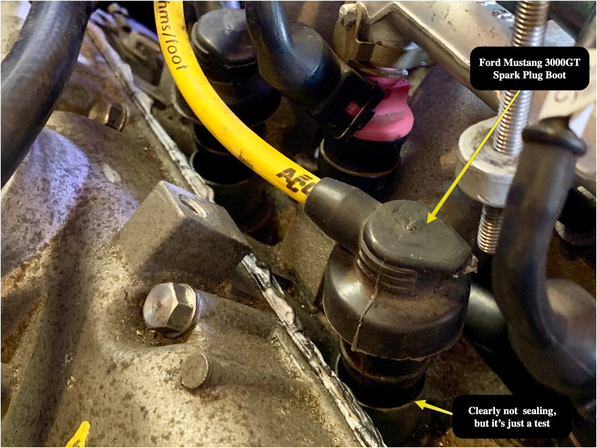
The 3000GT plugs fit just fine in the 3.0L engine’s spark plug ports, although they don’t seal properly. It’s fine for testing purposes, though.
Actually remembering to crimp on the weather seal on the left, which I forgot for many of the wires, like the one on the right. The original DMC bulkhead connectors don’t have any weather seals.

Wiring at the coil pack. I used plain white wires for the banks and a red wire for the 12v power.

4 pin GM Weather Pack connector to link the coil pack to the EDIS module via the updated bulkhead connector.
Trying to Fix the Coil On Plug Wiring
My best guess as to the problem with the coil-on-plug setup was that when I re-routed the harness, I pulled too hard on the coil wires and basically broke at least one of them. I didn’t break it completely, but I expected that a few strands were still connected, and a lot of current was running through that last bit of wire. Googling suggested that EDIS is sensitive to issues with the coils, which could be extended to damaged wiring. This explains why I’d see spark when visually testing it, but why the timing would be so far off — broken wires were affecting EDIS by virtue of the current draw. I don’t have evidence of this, but it makes sense.
I ordered new five foot lengths of 16 gauge yellow/white, yellow/black, yellow/red and green/orange wire from 4RCustomsWire.com, mostly because they had good prices, short (five foot) lengths available, and free shipping. Strangely, the 12v wire to the coils seems slightly thicker than 16 gauge, but that might just be the insulation. Having thicker wire for one wire in a circuit while the rest of it is smaller makes no sense, as the smallest gauge in a circuit is effectively the gauge of the entire circuit. I had trouble finding specific information on what size wire to get, but the MegaManual suggests 16 gauge for wires that drive the coils directly from MegaSquirt, and my wire strippers suggested it was 16 gauge when I installed my coil pack test, so that seems about right. Also, I couldn't find 14 gauge striped wire. That’s not a reason to avoid 14 gauge, but it implies that if striped wire isn’t common at 14 gauge, it probably isn’t 14 gauge.
New Coil-On-Plug Boots
Something else I noticed is that the new 3.0L wires I got held onto the spark plugs significantly better than the ones that came with the engine. I decided to modify one of the wire sets to create new boots for my coil-on-plug setup. Dave showed me how to remove the boots from the wires: first, spray where the wire goes into the top of the boot with silicone spray, then slide a pick or small screwdriver between the wire and the boot on two points on opposite sides of the wire, one after the other, to break the wire loose a bit. Then simply pull the boot off. I found some of the boots could. simply be pulled off without silicone or poking.
After spraying down the boot and wire with silicone lubricant, insert a pick on either side of the wire to loosen it from the boot, and then firmly pull the boot to slide it off the wire.
Using wire cutters to remove the top of the boot.
The boot pressed onto the coil, using a vice to hold the coil in place.
The tops of the boots have to be cut off to insert the coil-on-plug packs into them. I used a pair of wire cutters and just spun them around the boot as low as I could. To actually install the coil, I mounted it upside down in a vice, sprayed the hole in the boot with silicone spray, and forced it on. It’s a tight fit, but it snaps on securely. I did this with the conductor spring already mounted on the coil.
Testing
I installed this new coil-on-plug harness in the car, and it still didn’t work. I had exactly the same problems I had before. I switched back to the coil pack and it worked just fine. I’m thinking one of the coils is bad, but for now I just want the car running, so I’m continuing with the coil pack.
Sourcing Coil Packs and Wires
The Mustang coil pack had short wires, and wasn’t really going to work for a long term install. I either needed new wires, or a new pack and wires. I decided to make my first trip every to a junkyard.
I found a Pick-n-Pull in Johnston, RI that had a number of 1990s-era Ford Explorers, Mustangs and other cars that use EDIS6 as listed on Wikipedia. I left with two coil packs in a “six pack” 2x3 arrangement that used clip-on wires, and about a dozen spark plug wires of various lengths, plus a three of coil-on-plug modules in case I want to try out CoP again in the future. I made sure to cut off the connector with a pigtail when removing the coil pack, since I’d need to wire these up as well. Total cost was around $150. This particular coil pack design is readily available new from Amazon and various auto parts suppliers for about $90; they were $40 each at the junkyard, but if I need a new one in the future, Ic an easily get it.
Mounting the Coil Pack
I cleaned up the wires and modules with some brake cleaner and figured out how I wanted to mount the coil pack. I decided to put it on the driver’s side firewall, since there was plenty of room there now. I used some leftover slotted “L” stock to create a simple bracket for the coil pack, then drilled two holes in the firewall and inserted 6mm rivnuts.
The EDIS 6 coil pack (right, cropped) with one clamp-on spark plug wire connected. Two steps of compatible wire ends are also shown (left). The connector pigtail is partially visible as well (bottom).
The old boot after being cut off with a utility knife, and the underlying wire and end. The end can be bent straight by hand for the new boots.
The coil pack mounted on a bracket fabricated from slotted angle stock.
The underside of the bracket and coil pack.
The four pin connector. Don’t forget to grab this when you get your coil pack from the junkyard.
Setting Up the Spark Plug Wires and Harness
With the pack mounted, I checked the length of the wires. I had two that were short enough for the driver’s side, and three that worked great for the passenger side. I used one that was a bit too long for the remaining driver’s side plug, but I could always go back to the junkyard to get a better length wire if needed.
I cut off the old boots from the Ford wires; this was simpler than pulling the wires out due to the bend in them. I then straightened the bend and slid on the 3.0L boots. These fit perfectly, and mounted securely in the heads.
The new boots fit snuggly in the cylinder heads and held securely to the plugs, much more so than the coil-on-plug did. I believe this is because the coil-on-plug relies on the boots to hold onto the spark plug well, or for the coils themselves to be bolted to something secure. The metal ends of spark plug wires themselves snap onto the ends of the plugs, holding more securely than just the boots along do.
I made a new a new harness to the coil pack. I found a wiring diagram online for the connector, and matched it up to my wiring. The coil pack’s spark plug wire connections are numbered for their cylinders, but that only works for the firing order of the original engine. It’s a safe bet that the coils are wired in pairs, so there are only a few possible combinations for the three pairs of wires. Some quick Googling found the firing order for the Ford Explorer: 1-4-2-5-3-6. This fits with the presumed pairing of coils (ie: 1 and 5, 4 and 3, and 2 and 6 firing at the same time). The 3.0L engine, however, is 1-6-3-5-2-4. The pairings matched, but the order was different. Really, it just meant swapping the 4-3 and 2-6 pairs, then rolling them one position to account for the 120 degree offset from Josh’s setup. Alternatively, I could change which wires connect to the harness so that the numbers on the coil pack match up.
What I actually wound up doing was just moving pairs of spark plug wires to different cylinders until the engine fired, just like I did with the other coil pack. This worked just fine and I had the engine running again in no time.
Fixing the Exhaust Bracket
At some point I noticed that the bracket for the exhaust had come loose. I had mounted my adaptor piece on the exhaust side of the bracket, and it apparently shook the nuts off the bolts released the adaptor. I fixed this by mounting the adaptor on the other side of the bracket so that the exhaust would always be pulling against the bracket instead of pulling it away from it.
My adaptor plate to the exhaust bracket no longer actually mounted on the bracket.
Mounting the adaptor to the back of the bracket ensured this would never happen again (the hanger nut still has to be tightened in this picture).
Initial Tuning: Warm Idle
To start, I turned off acceleration enrichment to remove a variable. There's no switch in TunerStudio to do this, but there's another solution that works just as well:
Move the MAPdot-TPSdot slider all the way over to TPS, then set the TPSdot threshold to 3276.0 (the largest value accepted). The AE isn't *technically* turned off, but there's no way it's going to actually do anything.
opethmike and FABombjoy on DMCTalk were particularly helpful in getting this tune going, including providing a process for me to follow. This is fairly similar to what is described in the MegaSquirt Setting Up Manual, but condensed down to the parts that are actually relevant here.
I also found this article about idle from DIYAutotune useful (and is almost exactly the same as section 3.6 in the MegaSquirt Setting Up Manual, but with some more dialog pictures). MegaSquirt sports two methods for idle control with an IAC:
Open Loop: This is a simple curve that maps coolant temperature to the number of IAC steps. The idea is that you want to gradually reduce the amount of air as the engine warms up, until the motor is completely closed when at operating temperature (192 degrees F for the 3.0L engine)
Closed Loop: Once the engine is idling properly when warm, you can switch to this to tell the engine to idle at a specific RPM by automatically adjusting the idle air motor.
Initially, we want to use open loop, because we need to get everything set up correctly when warm before we can switch over to closed loop.
But most importantly, for this initial setup, we don't care about the warm-up stage. We just want to get the engine up to operating temperature so that we can get it idling properly when warm. Being warm removes a variable (temperature change), so it's much easier to tune at this point.
Open Loop Tuning: Getting the Engine Warm
You can mess with the VE table to get the engine warm with the AFR and RPMs you want, and that’s basically what I did. An alternative method is to set up the Warmup Enrichment curve and the Idle Warmup/Duty Steps curve. These are related, and are actually fairly simple:
Warmup Enrichment adds a certain percentage of extra fuel to the VE table based on the coolant temperature.
Idle Warmup Duty/Steps adds extra air to the engine by changing how open the IAC is baed on the coolant temperature.
So one adds more air, and the other adds more fuel. Which one you want to adjust is determined by the AFR and RPMs, which opethmike suggests should be around 12.5:1 when cold and gradually increase to 14.7:1 when fully warm. Adding air increases the AFR, while adding fuel decreases it. Remember that these are applied to whatever values are in the the VE table for the current engine MAP and RPM, but the initial generated VE table should be pretty close.
When fully warm, the warmup enrichment should be at 0%, and the IAC should be completely closed (0 steps). At that point the fuel is entirely determined by the VE table, and the air by the throttle screw, and you are in warm idle.
To get the engine warmed up properly the first time, I opened those windows, started the car, and kept an eye on the AFR, RPM and CLT gauges. At this point you ignore the RPM, but it’s good to see. Then you adjust the curves until the AFR was between 12.5:1 and 14.7:1 (depending on the temperature). Once the engine is at 192 degrees, the IAC should be closed and warm-up enrichment should be off.
Eventually, you can choose between closed loop and open loop for your warm up. If you like messing with curves, open loop is for you. But once you have a good, stable warm idle, you can let MegaSquirt do the work for you and switch to closed loop. You just pick your idle RPMs, and MegaSquirt adjusts fuel and air (via the IAC) to keep it there. There are other settings, including a curve that you can tweak if you want, but but it pretty much takes care of itself. But going closed loop without a good warm idle will just introduce more variables into your tuning, and make it difficult to get a good warm idle.
Switching to Closed Loop
The coil pack switch-over happened after I did the open-loop tuning, and I’d lost it while diagnosing those ignition issues. Now when I started the car, it shot up to 2000 RPM and stayed there. After worrying about a vacuum leak for a bit, it became clear that the problem was the idle air valve. Closing the IAC completely with the IAC testing features of TunerStudio brought the idle back down, although I had to adjust the throttle stop screw to keep the car running. I was able to get a good idle, so I decided to get the warm-up situation figured out.
After asking about this on DMCTalk, I switched over to closed loop at FAMBombjoy’s suggestion. This was pretty simple to set up. Closed loop adjusts the air (via the IAC) until the RPMs are at the desired level. This is specified by a curve describing RPMs at a given coolant temperature.

The closed-loop targets ranging from 1000 RPM when cold to 790 RPM when hot.
To turn on closed loop, go to Idle Control and change the Algorithm to Closed-loop. I left all of the settings at their current values, including the 200 homing steps I’d previously set for open loop.
Next open the Closed-Loop Idle Settings. I changed the Idle Valve Closed Steps to 0 and Idle Valve Open Steps to 200. This matched what I’d found when using test mode. The “Open” and “Closed” terminology feel backwards to me here, since for my IAC 0 steps is fully retracted (and thus lets the maximum amount of air through), and 200 is fully extended (thus allowing no air through), but it seems to work fine. The defaults (about 40 closed and about 138 open) left the valve open too much and it never got down to the RPMs I wanted. I left all of the other values alone.
Next was the Closed-Loop Idle Target RPMs. This curve lets you set what RPMs you want for a given engine temperature. The default is 1500 RPM when cold, which I felt was a bit high for how loud my car was. I found this interface a bit weird to use. Notably, it’s hard to click on a pint in the graph, but the box-select (click and drag) worked well, so I just did that. I set it so that it was at about 1000 RPM at 70 degrees, and 790 RPM at 140 degrees. 140 just happened to be the default value in TunerStudio; the engine is fully warm at 192 degrees, but at 140 degrees it seems too be idling reliably at ~790 RPM, so I left it like that.
To make this easier, the “…” button in the top-right corner can be clicked to show the values of the graph points. From here you can numerically edit the values, and you can interpolate the cells with the rightmost button in the toolbar. With this I was able to just set the first and last points, then interpolate the rest.
Before going any further, I closed the throttle adjustments screw all the way. There was no need for it to be open at all — MegaSquirt would now use the IAC to keep the car at 790 RPM to compensate for a completely closed throttle, even when extra loads on the engine kicked in, like the A/C. In fact, opening the throttle could cause the car to idle too high, since the automatic adjustments can’t drop any lower than that.
I started the car again, and it shot up to around 2000 (which is what it hits when the IAC is fully retracted), but quickly dropped to about 1000 RPM as it closed the IAC, and then slowly decreased further as the engine warmed up, settling on 790 +/-30 RPM or so. I could reduce the initial RPMs by changing the Idle Valve Open Stops to 150 or so, but I decided to tinker with that later.
While the engine warmed up, I continuously adjusted VE table to keep the AFR in the 14.7 range. I just didn’t want to have glowing headers again, and keeping it in the 14.7 range significantly reduced the fumes in the garage (I still had the garage door open, of course). I had also forgotten opethmike’s advice to have the AFR in the 12 range when cold, increasing to 14.7 when warm, but it worked out. On another startup I tried using the warm-up enrichment table (which is what you’re supposed to use) to bring the AFR down to reasonable levels, but I couldn't seem to get that do anything useful, while adjusting the VE table had immediate results. Later I would use the WarmUp Enrichment Autotune feature of TunerStudio, which automatically figures out the ideal fuel using a separate enrichment curve. For now I just wanted idle to hold properly when warm, which it was.
Setting Idle Zones
Now that the engine was warm, I also re-defined the second column of the VE table to 900 RPM, then adjusted the cells the car was idling at to as close to 14.7 AFR as I could. I set the four adjacent cells (based on which cells the idle was closest to) to the same values. The idea is that MegaSquirt will interpolate between these four equal values, thus always having the same value and being completely stable at idle.
After turning the car off, I made sure there were smooth transitions in the VE table from the idle cells I modified to the rest of the table. We don’t want any big jumps here. I interpolated the the rows above and below the idle zone, all the way to the edge of the graph. For the columns to the right, I first increased the near-rightmost column (not the rightmost ones, which are a bit lower than the original ones) to be higher than the idle zone, then interpolated across to them as well. I left everything else to a future auto-tuning session.
Finally, I set up an “idle zone” in the Timing Advance table, as suggested by FABombjoy on DMCTalk. I changed the second column to 900 RPM, then set the cells above, below, and to the left in a 3x2 grid to 14.0 degrees centered on the 40 kPa row. This would lock the timing at 14 degrees when around my target 790 RPMs, which should keep the idle nice and smooth.. I pretty arbitrarily chose 14 degrees. The 2.8L engine is 13 degrees +/-2, but I couldn’t find any specs for the 3.0L engine (the manual just says that it is set by the original ECU and is “not adjustable”, which was no help). 14 seems close enough.
…And the Starter Died
I tried another start, and nothing happened. No cranking, no solenoid clicking, nothing. Applying 12v directly to the starter solenoid wire with a PowerProbe didn’t do anything at all.
I pulled the starter to bench test it. This was a huge pain, as the exhaust headers were in the way, and needed to be Tetris’ed out past the oil filter and alternator. I also failed to remember to disconnect the battery and got some nice sparks when the starter wires touched the engine and grounded out. Once removed, I connected a jumper cable between the frame and the starter casing, then used the PowerProbe to fire the solenoid… which worked fine.
I still don’t know what was wrong. The heavy wire to the starter was slightly loose, so I tightened it up and reinstalled it back in the car. It seems to work just fine now.
And with that, it’s finally time to actually drive this thing. I mean, drive it slowly around the block and try not to stall it, but still, time it’s time to drive, after nearly five and a half years.