
Wiring, Installing the New Harness and Fuel Injector Refurbishing
Joe Angell
With the bulk of the now-unused wiring out of the car, the next step was to make any changes necessary to the Josh's harness and set up my own. I also made my own wiring diagram to make sure I understand how everything is intended to be hooked up, and to deal with some changes I needed to make to the harness.
A New Wiring Diagram
Josh's diagram was a great reference, but there were going to be just enough changes that I wanted to make my own. This would also ensure that I really understood where everything was going. Also, Josh wasn't able to include the DB37 pin connector that goes to the MegaSquirt, so I needed to solder the wires to the connector anyway.
I used the vector graphics application Autodesk Graphic (previously called iDraw before Autodesk bought it) on the Mac to make my diagram. It's an app like Adobe Illustrator, and serves my purposes pretty well. Like Josh, I went for a more representative wiring diagram rather than an abstract one, drawing an outline of the engine bay and parcel shelf and placing components roughly where they would go in the final installation. This results in a bit messier of a layout, but it can be easier to find what you're looking for. That said, I see why abstract diagrams are commonly used.
Updated August, 2016:
Updated LC2 wiring to note that even though it is a sensor, its black wire must be connected to ground and not sensor return, as the LC2 also has a heater and other high-current requirements that will introduce noise if connected to the signal return wire. The dedicated yellow (to pink) wire is used for communication.
Updated the 3.0L oil sender to be used exclusively for the oil light, and added the 2.8L sender for the gauge. While the 3.0L sensor can theoretically do both light and gauge, it doesn't seem capable of driving the 3.0L gauge.
Updated January, 2019:
Re-ordered the TPS wires to match the actual connectors.
Added jumper information for disabling the TPS for MAP-only setups.
Added EDIS coil pack wiring as an alternative to coil-on-plug.
Updated September 2019:
Added A/C idle up wiring.
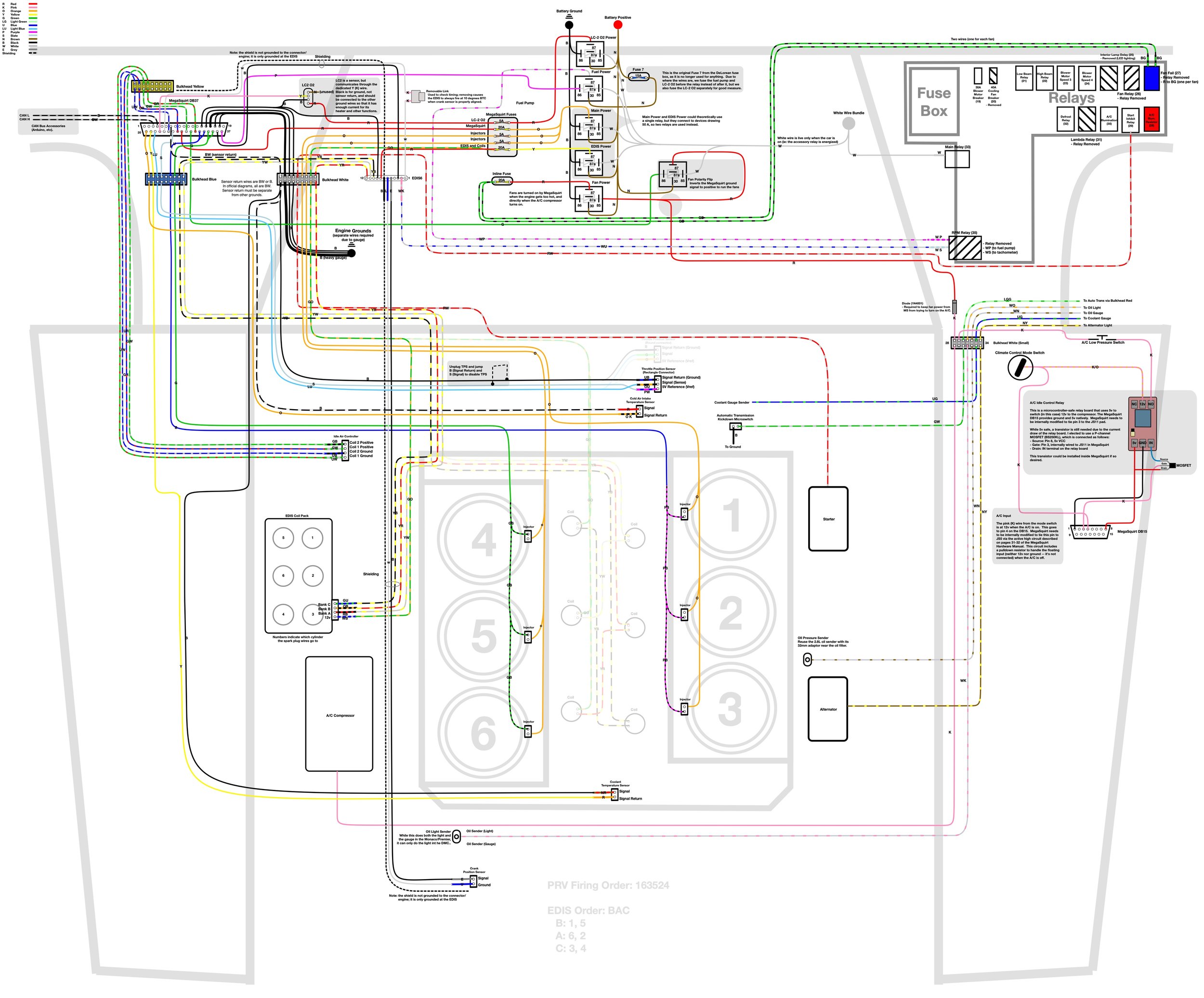
Click here for a PDF version of the wiring diagram.
Building the Harness
To be honest, there wasn't much to do here -- I had Josh's harness, so the bulk of the work was done for me. The main issues came from consolidating the Red bulkhead connector's wiring into the Blue and White (9 pin) connectors to work around the fact that I'm still using the original Red connector for the automatic transmission, as I mentioned in the previous post. I also had to add a new Yellow connector for the idle air controller wires (Josh had just run them through the firewall separately), and rework the pins on the White (7 pin) connector to account for Josh's changes and the automatic transmission.
The largest task was simply mapping and soldering the wires to the DB37 connector for the MegaSquirt, which Josh wasn't able to include with the harness. This is when I drew up my diagram, and where I made sure that I understood what every wire did.
(Almost) all of the wires soldered to the DB37 connector (I forgot the pink one to the EDIS6). Also note that the shield cable should not be grounded here; it is only grounded at the EDIS.
Final assembly with the cover installed on the connector and strain relief clamped on the wires.
Idle Air Controller Wiring
I had to do some tests for this one. Josh used two green wires and two blue wires for the IAC before linking them to their distinct striped wires, but the sheath that bundled all four of them together made it hard to tell which wires went to which pins on the MegaSquirt DB37 connector. Once you figure out which pins go to which pair of wires, you still need to make sure you hook up the right wire to each pin, as reversing them will cause the solenoid to open when it should be closed and visa versa.
The first step was to figure out which IAC I had. I quickly found a diagram explaining how to check by looking for ~50 ohms of resistance between the center pins wth a multimeter. The Jeep IAC (part 53007562) that I had seems to match those conditions, so I used the first diagram. I used a then used my multimeter as continuity tester on the connector on Josh's harness all the way through the wires to the DB37 to make sure I was hooking up the right wires to the right pins.
Throttle Position Sensor Wiring
Josh had originally a TPS with a round plug, and his harness reflected that. The new Jeep throttle came with a rectangular GM-style plug, so I needed to replace the existing plug on the harness with the new one.
The MegaSquirt manual details how to test the TPS with a multimeter:
Switch it to measure resistance. The resistance between two of the connections will stay the same when the throttle is moved. Find those two - one will be the +5 Vref and the other a ground. The third is the sense wire to the MegaSquirt® controller. To figure out which wire is the +5 Vref and which is the ground, connect your meter to one of those two connections and the other to the TPS sense connection.
If you read a high resistance which gets lower as you open the throttle, then disconnected wire is the one which goes to ground, the other one which had the continuous resistance goes to the +5 Vref from the MegaSquirt® EFI Controller, and the remaining wire is the TPS sense wire.
Easy enough. For mine the middle orange/black wire was the sense wire, the black/blue wire was ground, and the dark purple/white wire was the reference voltage. Then it was just a matter of stripping the wires, removing the old connector from the harness and soldering the new connector in place.
I then hit the TPS with a wrench and popped the (supposedly glued on) cap off the end,causing the spindle and spring inside to fly off. After spending 20 minutes hunting them down, I almost got it back together when the wipes on the spindle broke off. The T20 screws were a pain to remove, and I manage to drop my screwdriver bit somewhere into the engine bay, never to be seen again. I cut the head of the screw off with a Dremel, pulled off remains the TPS, and unscrewed the remainder of the screw with vice grips. Luckily, this TPS is easy to find -- Amazon identified it as an OEM 99053 Throttle Position Sensor for under $25. I bought new hex bolts to hold it to the engine; I'm not a fan of easy-to-strip screws.
Testing which wire is which on the TPS with a multimeter.
New soldered wires on the throttle position sensor connector.
Bulkhead Connectors
As I mentioned before, I needed to continue to use the Red connector for the automatic transmission, so I removed it relocated the pins from Josh's harness to empty holes in the Blue and White (9 pin) connectors. I had run out of pins for the four wires needed by the idle air controller, but since the old Yellow connector was removed entirely, I was able to replace it with a new connector, crimping the wires into those pins.
The White (7 pin) connector wasn't detailed on Josh's diagram, as it seemed to just connected to standard engine connections. However, for some reason he'd relocated all but one of the pins to different parts of the connector. I found it much easier to remove the male pins on the other side of the harness to make the connectors match. Even so, I had two small changes.
The first was to the reverse light switch, which Josh had run directly from manual transmission reverse switch through the White (7 pin) connector via two wires. Since I retained the Red transmission connector, I didn't need those wires rerouted, so I simply cut them out of the harness. The automatic transmission does need a kickdown switch, though. On the 2.8L engine this is mounted with the wide open throttle (WOT) microswitch, and tells the transmission to kick down a gear when the pedal is on the floor. I ran a separate wire from the switch through to the connector at one of the now-unused reverse light wires, and grounded the other end of the switch to the engine as per the standard DeLorean wiring diagram. The WOT microswitch isn't needed at all, as MegaSquirt uses a TPS to monitor the exact throttle position directly.
Another change to the original wiring is that Josh ran the starter wire (white/red) so that it went through the white (9 pin) connector, instead of using the original white (7 pin) connector. This was a simple matter of attaching the existing white/red wire from the starter relay to the pigtail he left on the new harness.
EDIS 6
Josh had included an EDIS 6 module with his harness. It was already connected to everything, so other than soldering the wires to the MegaSquirt DB37, there wasn't much to do here. I made good use of the MegaSquirt manual to figure out how the pinout worked, just to ensure that I really understood everything when creating my wiring diagram.
An important detail of the EDIS wiring is to make sure that you can disconnect the white wire from pin 1 of the EDIS system. This allows you to run the EDIS in "limp home" mode, but more importantly it allows you to make sure your crank sensor is aligned correctly at 10 degrees before top dead center (BTDC). Josh included a removable link that makes this very easy to do. I'm not sure where he got it, but it's pretty handy. Another solution is just to use a male and female blade connector, and simply pull them apart when needed.
Complete wired EDIS6 module. The removable link is connected to the pink wire, with the grey link removed in this picture. (The blue wire is incidental, and not part of the EDIS6 harness.)
Shielded Wiring
A quick note about shielded wires: For most of the installation, simple unshielded wiring is fine. The only time you need shielded wiring is when dealing with A/C signals, as RF noise from other wiring, stray radio signals, etc. could introduce errors in the signal and cause the modules that read those signals to misinterpret them. Shielding simply keeps the noise out. The only place you encounter A/C signals in the original DeLorean wiring are are from the distributor to the ignition module. With MegaSquirt, the only A/C line is from the crank sensor to the EDIS module, and the EDIS module to MegaSquirt.
An example of a shielded cable is a headphone cable -- two normal wires wrapped in a spiral of bare shield wire, all wrapped up in a plastic sheath. The spiral of shield wire keeps RF noise from affecting the wires it wraps by by drawing the noise to the grounded end of the shield, thus ensuring that you get a clean signal at the other end. Josh even used a stereo headphone jack and connector on for the shielded crank sensor cable so that it would be easy to plug and unplug as needed. The wires within the cable should remain shielded as long as possible before they are connected to their components, with as little wiring beyond the end of the shield as possible.
For a signal cable like this, the shield is grounded at only one end; grounding at both ends defeats the shield. For example, in the setup I got from Josh the crank cable shield is only grounded at the EDIS end, and not at all the crank end. Similarly, the SAW/PIP line from the EDIS to the MegaSquirt is also only grounded at the EDIS end.
Note that there are exceptions to the "ground only one end" rule, such as for audio cables, which are grounded at both ends, and motor cables, where you want to shield everything else from the noisy signal inside. I'm far from an expert on grounding shielded wires, so be sure to do some research on your own if you have any questions at all about it.
Googling also suggested shielding the TPS wire and O2 wires (I believe my wideband O2 sensor wire came shielded), but that it shouldn't be necessary for anything else. Since Josh didn't shield the TPS wire, I'm not going to worry about it.
As an aside, another simple way of doing shielding is simply to twist the wires. Ethernet and telephone cables do this, for example; it's know as twisted pairs. It's not as good as actual shielding, but it's simple and useful for certain applications. It seems you can also buy shielding tape and looms that can fit over existing wiring, which I may look into if I decide to shield my TPS in the future.
Crank Sensor Shielded Cable
UPDATE: December 2018: Josh later mentioned to me that the headphone connector was not a good idea. Every time it rained he had to unplug it and plug it back in. Others on DMCTalk were aghast at the idea of a disconnect here, especially in the form of a headphone connector. I was likely getting some noise from this as well. In the end, I removed the connector and ran the wire through the driver’s side of the firewall and to the EDIS module. This eliminated about half the length of the shielded wire as well.
Original Post:
Josh had included a shielded cable from the crank position sensor to the EDIS module, with a stereo headphone jack about half way down the harness so that you could separate the cabin and engine harnesses completely, just like you can do with the bulkhead connectors. For whatever reason, the plug was there, but the jack was missing. After finding that the plug didn't seat reliably in my new jack, I replaced both.
The VR sensor has no polarity, which means that the sensor and return wires are defined entirely by which pins they're connected to the on the EDIS -- either wire can be connected to either part terminal on the VR sensor connector. The shielded cable from the EDIS to the MegaSquirt is a different story, as each of the wires are used for different things, but the VR sensor is arbitrary.
After failing to find some decent 3.5mm jacks and plugs locally or on Amazon, I ordered a pair of each from Adafruit. Solder is pretty simple: the wires attach to the short posts and the shielding to the long post. I found that the easiest way to tell which which post went to which part of the jack was to test the plug side first with a multimeter, touching different parts of the plug to the post with the leads, and then connect the plug to the jack to test the leads there. This wasn't strictly necessary, as since the VR sensor has no polarity it didn't matter which one was connected to which; I was just curious.
I got the female jack all soldered up when I realized I'd forgotten to put the strain relieve and outer casing on the wire first. I then ruined the jack trying to unsolder the wires. Luckily I bought two of them. The second time I got it right. To make sure everything worked properly, I used a multimeter in continuity tester mode on the pins of the connector and the pins of the EDIS. I also tugged on the jack and connector a bit to make sure that it wouldn't come slightly loose while driving and ruin the connection.
Since the jacks I got had metal frames, and since the shielding is grounded to the frame, I wrapped the connectors with self-fusing tape after they were installed in the car to ensure that they didn't touch any metal anywhere and defeat the shield.
The jack (left), a plastic sleeve that this jack came with to reduce the chance of the wires shorting against the shielding, the strain relief "spring", and the outer casing (right).
The newly soldered and assembled 3.5mm stereo headphone jacks on the shielded wire.
Fuses, Power Relays and the Fan Polarity Relay
A total of seven (7) fuses are required in total:
10A: Fuel Pump
5A: LC-2 O2 Sensor
20A: MegaSquirt
5A: Injectors (first bank)
5A: Injectors (second bank)
20A: EDIS and Coils
20A : Fans
I'm not totally sure why you need separate fuses for the left and right banks of injectors, but I followed the spec and did it as per Josh's diagram and the MegaManual. I also added some corrections, such as upgraded the LC-2 to a 5A fuse from Josh's 1A as per the documentation. Some of the fuses are likely unnecessary, but it's not hard to add them and they won't do any harm.
A total of four power relays are needed for the MegaSquirt, plus one for fan polarity issues:
Update May 28, 2016: I originally wired the LC-2 and the fuel pump to the same relay, as per Josh's original diagram. Clearly this worked for him, but I'm slightly more paranoid -- the LC-2 manual points out that you should really wire it up separately. Also, the fuel pump is only briefly powered (primed) by MegaSquirt if you don't actually start the car, which means that the O2 sensor will be off until the car is running. This probably isn't a huge deal -- you don't need an O2 reading when the car is off -- but it's easier to work on the O2 sensor configuration when it always has power.
Fuel Power is switched from a signal from the MegaSquirt, and drives current through a 10A fuse to the fuel pump via the white/purple wire previously connected to the RPM relay. It also requires power from the ignition relay's white wire, meaning that the car must be on and MegaSquirt must be sending the fuel pump on signal for the pump to the powered.
Main Power, EDIS Power and LC-2 O2 Power are all switched with the ignition via the ignition relay's white wire. Three relays are used because the total power for these two circuits tops out around 50A, and automative relays are usually only 30A or 40A. The LC-2 is also susceptible to noise, which is why it has its own dedicated power. The main power relay supplies the MegaSquirt itself and the injectors, while the EDIS power relay supplies the EDIS unit and the coils.
Fan Power is switched from MegaSquirt via the repurposed FIDLE line, and in turn powers the two cooling fans via the green/black wires previously connected to the fan fail relay. The catch is that FIDLE provides ground, not positive -- the fans would be running when the car is cold instead of hot -- so you need to flip it with a Fan Polarity Flip relay in the circuit.
These are standard 40A automative relays. I bought a set of ten relays and sockets off eBay for $25; I only needed six, but having spares doesn't hurt, and these relay sockets can be linked together much like the ones in the DeLorean's existing relay compartment.
I also ordered some extra 18 gauge striped wire from EFIConnection.com, which would be used to run wires from the harness to the stock wiring.
Injector Connectors
After the original package Josh sent me was lost in the mail, he got together another set of parts to replace them, including some new injectors. These were EV6 style injectors with USCAR connectors. They didn't quite fit the fuel rail clips properly, and the connector was so tight against the clip that it was difficult to secure them, but I was able to do it.
The main issue was that the connectors weren't right for the Jetronic/Minitimer connectors installed on his harness, which fit into the EV1 style injectors that his engine originally had. He did include new USCAR connectors for the harness, though, allowing me to solder them on in place of the Jetronic ones. The EV1 and EV6 injectors are the same length, so height wasn't a problem; it was just the connectors and the clips.
About a year later, the box of lost parts finally arrived, including his intake manifold and its EV1 style injectors. I thought about sticking with the EV6 injectors, as they were already mounted and should work fine, and supposedly they produce a finer spray patter that is useful in performance applications (which mine isn't), but the fit of the clips concerned me a little, and it seemed like it was going to be a lot easier to just replace the injectors than replace connectors. I also didn't have appropriate wire lying around, and Josh had very nice boots and covers on the pre-installed connectors already.
So that's what I did -- I swapped the plugs and connected the harness straight up with no modifications. I can upgrade to EV6 with Jetronic/Minitimer connectors in the future if I really want to, but I doubt the likely very slight change in performance will be worth the few hundred dollars.
It's also worth noting that you can buy an adaptor kit to connect EV1 injectors to EV6 connectors for under $20 on Amazon. I was tempted to just do that, but decided that just swapping the injectors would be a better way to go.
If you do need to wire the connectors yourself, the injectors are simple spring-return solenoids, so it doesn't matter which wire goes to which side of the injector, which keeps wiring simple.
Replacing an Injector Pintel Cap
The pintel (the bit with the holes where the fuel sprays out from the injector) has a plastic cap that helps it seat properly in the manifold. While Josh's original EV1 injectors looked clean and in good shape, one of them had a cracked pintel cap. I wasn't sure how serious that was, so i decided I'd replace the cap. It turns out you can buy an 8 injector EV1 service kit for $20 on Amazon, so I figured I'd get that for future service as well.
I found some videos on YouTube explaining how to replace the cap. I used a heat gun to soften the cap's plastic, and then pulled it off with a pair of pliers, taking care not to damage the pintel itself. The ring and spacer come off easily after that. I then just slid on the new ones, rested, the cap on the end the cap on the end, and heated the cap again with the heat gun. Once it was warm, I tapped it firmly with a small hammer until it was seated completely against the end of the pintel. The whole process only took a few minutes, and I have plenty of parts left over to do any others should the need arise.
After installing the cap, I noticed that the new cap sat closer than the caps on the other injectors. It looked like the old caps might actually be spraying some fuel into the cap and dropping down. I decided to just replace all of the caps. The uncracked ones were much harder to get off; cutting them with a knife would probably make it easier, but my Leatherman's knife really didn't do the job here. I heated them with the heat gun and pried them off for the most part.
Cracked injector pintel cap.
Ready to install the new spacer, O-ring and pintel.
Newly installed pintel cap.
An injector with an old cap (left) and a new, noticeably more flush cap (right).
I also compared one of Josh's newer injectors against one of the ones that was originally in the 3.0L engine when I received it. The new injectors have four small nozzles for a finer mist, while the old injectors have a single pin in the center the the fuel mists around. Presumably the new design is better, or they'd still be using the old one.
One of Josh's new injectors with four nozzles, and one of the originals with a pin that came with the original engine.
Replacing an Injector Filter
While I was at it, I figured I'd replace the injector filters and top O-rings as well. I decided to practice on one of the original 3.0L injectors first, before risking damage to the ones from Josh. I followed the simple instructions that came with the kit, and twisted a screw into the injector a few turns, just enough to get a grip (the instructions actually said to mount the screw into the vice, not the injector, but same difference). I then pulled on the screw with pliers, wiggling it back and forth until it popped out. A couple of times I hadn't screwed the screw in far enough and just pulled the screw out, so I had to try again, giving it a few more turns.
Once the old filter is out, the new one is placed into the top of the injector (still mounted in the vice) and firmly tapped into place with a hammer. I was a bit worried about hitting too hard, and once I tapped lightly enough that the filter popped out and rolled across the floor. Two or three strong taps is all it needs to sit flush with the top of the injector.
I popped on the new O-ring, and that was it -- six newly refurbished injectors, and enough spares for three more.
The screw partially turned into the top of the old filter, before using pliers to rock the screw back and forth to lift the filter out.
A new filter (back left), the filter from the original Eagle engine (back center), and the filter from one of Josh's injectors with the screw still in it.
More Wires: Using Multiple Thinner Wires In Place Of One Thicker Wire
To hook the harness up to the stock electrical system, I needed some more wires. To figure what gauge I needed, I used the this handy chart that shows gauge for amperage over the total wire run. Note that "total wire run" is from one terminal of the battery to the other, including any grounds, not just the length of the piece of wire from, say, a fuse to a relay.
I ordered some 18 gauge striped automotive wire from EFI Connection, and some 16 gauge solid colored automotive wire from a seller on eBay. What I really wanted was 14 gauge or 12 gauge wire, but it was hard to find colored wire at decent prices in those sizes. Some googling revealed that you can use multiple smaller wires to carry the current of a single larger wire. The rule is that to get a gauge of N, you need two pieces of N+3 wire, or three pieces of N+5 wire. Two 16 gauge wires therefore can carry the current of a single 13 gauge wire which was fine for my purposes. I similarly bundled other wires as needed to match the amperage the wire was expected to carry over the circuit's total run.
Relay Sockets and Terminals
I originally planned on mounting my new relays separately from the original ones, and bought a batch of ten interlocking sockets with pigtails from eBay for $25. Once I'd removed the old relay wiring from the car, however, I realized I had exactly six empty relay slots in the stock relay compartment (Lambda, Fan Fail, Fan Relay, Light Delay Module, and two spare sockets). That meant that I could put my relays in in the same place as all the original ones. Even better, I could reuse some nearby wiring, such as the ground wires to the sockets and some now-unused always-live brown wires.
The trick was that I had no terminals for those relays, and it's surprisingly hard to find them. It was surprisingly difficult to figure out what these are called: they're Mini ISO Relay Terminals, 0.250 x 0.032 mm for 18 to 14 gauge wire. The ones I got are from TE Connectivity, manufacturers part number 42238-2, and they fit perfectly. I bought them from Mouser Electronics.
While the new relays would integrate with the original ones, my new fuse box, the MegaSquirt, EDIS6 and LC2 would go behind the driver's seat due to space issues behind the driver's seat.
Installing the Engine Bay Harness
With the new injectors in place, I installed the engine bay harness. It took a bit to figure out how to run everything, but it wasn't TOO bad, overall...
Injectors: These were in so still so tight that I had to unbolt the rail to get enough play to fit the plugs onto the injectors. The harness was laid out so that the injector plugs ran down the passenger side, then looped back up along the driver's side, forming a "U" shape.
Coils: I had to do a little tracing on the spark plug wire, as my handling of the harness had torn of the masking tape labeling. I also wound up updating my wiring diagram slightly to match the true color of the wires. Overall, though, it wasn't a big deal.
Throttle Position Sensor: Simply plugged in, once I reinstalled the TPS itself.
Coolant Temperature Sensor (Water Pump): This is the sensor that provides the engine temperature to the MegaSquirt. It plugged right in.
Idle Air Controller: Plugged right into the harness.
Alternator: Easily plugged into the connector on the side of the housing.
Crank Position Sensor: Once again, I simply plugged the harness into the sensor and I was good.
Intake Air Temperature (IAT): This is ideally at the air box for a proper cold air reading, but for now I just plugged into to the sensor mounted on the throttles elbow that Josh had installed. He had two connectors, labeling them together as "open or closed filament", but both tied to the same wires, so I'm not really sure if it even matters which one is used.
Starter: This white/red wire normally runs right to the starter solenoid. I have a somewhat different setup where the wire instead runs to a relay that switches main battery power directly to the starter. This works around some weak power problems I've had in the past. It also make it easy to crank the starter from the engine bay by removing relay and jumping the appropriate pins -- I even have a push button with spade terminals just for that purpose.
And now the trickier bits Its worth noting that everything from this point down on the engine bay side of the harness is not critical to engine operation -- the MegaSquirt doesn't use any of this. Instead, they drive gauges on the instrument cluster.
Oil Pressure Sender for Gauge and Warning Light
Josh's diagram showed DeLorean style oil senders, because that's what he put in his car, and I hadn't actually looked to see if they were present until I tried to hook up the harness -- they weren't. Instead of mounting a sender on the passenger side near the oil filter, there is simply a large brass hex-head plug. There is a sender mounted on the driver's side of the engine, though. This is mentioned on page 40 figure 100 of the 3.0L Engine Overhaul manual. Josh reported having problems getting that to work, which is why he used DeLorean senders instead. The oil warning light sender has the same thread as the sender on the 3.0L engine, but to install the gauge sender he had to remove the brass plug and tap an NTP thread through the center of it (I later discovered that the 2.8L uses an adaptor, which is available from DeLorean as part 102821 and seal washer 102013).
If possible, I wanted to try to use the sender that was already on the engine. This sensor has a three pin connector, but only one the center pin is actually present. Some Googling revealed this to be a standard GM-style oil pressure connector. I found a pigtail at WiringDepot.com for under $15.
I wanted to test the sensor, which meant getting it out of the car. This required a special socket with eight faces instead of the usual six, but they're readily available at auto parts stores for under $10. The one I needed was 1 1/16" in diameter, and 2 3/4" deep. Luckily, these are readily available at any auto parts store for under $10. With one in hand, the sender came out pretty easily.
The Premiere/Monaco Service Manual says that it is a variable resistor, presumably grounded to the engine, since the connector has only one wire. I wanted to test this, so I clamped it in a vice, putting a piece of wire between the vice and the body so that I had something to clamp my multimeter to, with the other probe connecting to the pin on the connector.
The next trick was applying pressure to the sender. I don't have a working air compressor, but I did have the pump-action Super Soaker that I'd used to clean out the oil/coolant gunk from the coolant passages in the engine block last year. After completely emptying it of water, I found that it perfectly sealed over the hole in the end of the sender.
The results i got were interesting. If you applied enough pressure, continuity was lost and you had an open circuit. But before that point, the resistance would change with pressure, meaning that this was indeed a pressure sender. dn010 on DMCTalk reported that he successfully used this sender for both the oil pressure gauge and the idiot light just by hooking both up to the single pin. Here's my theory on how this works:
With low pressure, there is little resistance, so the circuit to the idiot light is complete and turns on.
With normal pressure, there is enough resistance that the idiot light can't turn on, but the gauge can move normally.
With too much pressure, the switch opens. A pull-down resistor on the idiot light could cause it to turn back on again to indicate a high pressure condition. The gauge could also peg at maximum with appropriate wiring.
So this one sender is able to present a low pressure warning, a high pressure warning and a gauge reading. Given this new information, I simply connected the gauge and light wires together and hooked them both to my new pigtail.
Update; August 2018: Unfortunately, the sender doesn't work with the DeLorean oil pressure gauge. It's fine for the light, but it pegs the gauge straight up, so it's not useful there. In the end, I wound up getting the 2.8L adaptor 102821 and seal washer 102013 from DeLorean Midwest, and installing my original 2.8L sender into that, which worked perfectly. This fits in the same location as on the 2.8L engine, right next to the oil filter.
The oil pressure sender (top right) and the knock sensor (center left).
Positioning the Super Soaker nozzle over the end of the 3.0L oil pressure switch for bench testing.
2.8L (left) and 3.0L (right) pressure switches side by side, connector end up.
The brass plug next to the oil filter where an oil sender would be on the 2.8L engine.
Testing the 3.0L oil pressure switch with a multimeter and a Super Soaker.
The 2.8L switch (left) has a cylinder on a spring that can be pushed by hand, but the 3.0L switch (right) needs pressure forced through the hole the bottom.
Knock Sensor
On the center bottom of on the driver's side of the engine is a knock sensor, or at least that's what the consensus is. It has a Bosch-style fuel injector connector is installed with a hex nut that can be removed with a 24mm wrench. I found a crows foot wrench was necessary to get it out; I didn't have any sockets of the correct size, and my open and box wrenches were too long to turn in the available spce.. This reveals a simple flat end on the back of the screw, and that the threaded hole doesn't go into the engine body (it goes into the engine wall, but not through he wall into the interior of the engine). I'm simply leaving it as is, unconnected.
Using a 24mm crows foot wrench on a socket to secure the knock sensor. The sensor is otherwise unused.
Final wiring of the crank sensor, oil sender (tied into both the gauge and light wires), and the unused knock sensor. Care is taken to ensure that the wires don't come in contact with the intake manifold by zip-tying them to the A/C tensioning arm.
Coolant Temperature Gauge Sender
There are three temperature senders on the 3.0L engine: one at the water pump (coolant temperature, or CLT, to MegaSquirt), one in the air box or at the throttle (cold air temperature, aka "intake air temperature" or IAT, to MegaSquirt), and one for the coolant gauge. Like the 2.8L engine, the 3.0L coolant temperature gauge sender is mounted on the passenger side cylinder head near the throttles. It's a little bit tough to reach, but not impossibly so, at least if you have the engine cover off. This sender has a two pin connector on it, Josh couldn't get this to work, so he replaced it with the 2.8L engine's sensor. As such, his harness has a single ring terminal on it instead of a compatible connector. AdmiralSenn on DMCTalk.org said that he was able to get it to work, though.
Being stubborn, I wanted to at least try to make it work. While I resisted pulling it out of the car due to its somewhat hard to reach location, I finally just removed it so that I could bench test it. Like the oil pressure sender, the Monaco/Premier Service Manual says that it is a variable resistor. I couldn't get it to actually work, though; I clamped it in a vice, connected an ohm meter and heated it up with a heat gun, but I couldn't even get continuity on it, much less resistance. I still had the 2.8L temperature sensor, as well as one from Josh's harness for the water pump, and when I tested them in the same way I both got continuity and the resistance dropped as the temperature increased, and then went back up as they cooled down, just as they were supposed to.
With it already out of the car, I decided that I'd just toss the inoperable sensor and use the 2.8L one, with teflon tape on the threads to ensure a good seal.. I wasn't sure where I was going to find a connector for the 3.0L one anyway. A 22mm (or 7/8") wrench is needed to remove and secure it, and an 8mm wrench to tighten ring terminal to the small nut on top. I attached the ring terminal first, but loose enough so that it could spin as I used an open ended wrench to tighten the sender itself. Once the sender itself was tightly in place, I used the 7mm wrench to tighten the nut and lock the ring terminal in place.
The 3.0L coolant temperature gauge sender (left), the 2.8L one (right), and an alternate sender from the water pump (middle).
The coolant temperature gauge sender is tucked behind the engine inside the "V" on the passenger side cylinder head.
Engine Grounds
There were a couple of wires on the harness that were identified as engine grounds. The length was just right to mount them to a free bolt on the passenger valve cover. Simple enough.
At this point I realized that I'd forgotten to reinstall the ground braid between the frame and the engine. This is easier to do when you're installing the mounts, as there isn't a lot of room between the engine and the short mount bolt,. There's just enough to make small turns with a 10mm open or box wrench, so you can do it, but it's annoying. The other end of the harness goes onto the long "bolt" (really a threaded rod with a nut on either end) that holds the engine to the mount. Two 17mm sockets with extensions are the easiest way to get those off.
I replaced my corroded engine ground braid with a new one from DeLorean.com. Instead of a braid, it's three heavy wires with ring terminals on the end. Oddly, the terminal that goes on the engine side was slightly too small for the bolt. I tried to drill it wider, but the drill got stuck and twisted the end off. A trip to the auto parts store later and I had some new heavy ring terminals. I don't have proper brazing gear (just welding stuff, and that's too hot for brazing), so I stripped the three wires, slid them into the terminal, clamped the whole thing in a vice, tightening the vice with a cheater bar until they were as flat as I felt I could make them without damaging the vice or myself. They're in there pretty well, and I'm not too concerned about them slipping off. All that was left was to slide the rings onto the bolts and tighten them down to the engine again.
Routing the Harness
Getting the harness to reach the bulkhead connectors was trickier than I had expected. Josh used the original 3.0L throttle in his car, which is actuated by cables pulling to the side. The Jeep throttle is turned 90 degrees, which means that the throttle cables have to do a 180 degree turn in a run by the passenger side of the intake manifold to pull the throttle arm towards the back of the car. Unfortunately, the harness was clearly intended to run right where the Jeep throttle arm sat.
The best solution I could come up with (short of using longer wires) was to tuck the harness into the valley between the throttle and the intake manifold, running it under the vacuum hoses and towards the bulkhead ports. This ensured that the wiring wouldn't interfere with throttle movement or the cables themselves, but could still reach the bulkhead without any problems.
I was now concerned about heat. The wires would now be tucked into the "V" and basically be pushed up against the heads. Automotive wire is rated to 170 degrees Fahrenheit, and valve covers can easily get to 160 F, and would likely get hotter in the valley. This meant that it was pretty likely that I'd wind up melting some wires. Some googling led me to thermal heat sleeves, which simply wrap the wiring and deflect heat away from the harness. I found a three foot long split piece with a one and a half inch inner diameter. It was sealed with velcro, which meant I didn't have to figure out how to run the wires through the end or cut it lengthwise myself -- I just wrapped it around the wires and that was it.
Engine harness routing (dashed green line). It runs from the bulkhead connectors, under the vacuum lines, and in a "U" loop over the top of the intake manifold. The thermal sleeve is mostly hidden from view, and protects the part of the harness nearest the cylinder head from heat in the "V" area of the engine.
Cabin Wiring
Back in the cabin, the other end of the harness needs to be connected to the rest of the car's electrical system. I decided to start from the relay compartment and move out from there.
Bulkhead Connectors
There was little to do insofar as wiring up the bulkhead connectors, as they were primarily connected to MegaSquirt and the EDIS module. I did have a few wires to run, though:
Starter Wire (White/Red). This previously went to another bulkhead connector, so I just removed the pin from the old one and plugged it into the new harness's White (9 pin) connector.
Relays
There are a total of six new relays: Fuel, Main Power, EDIS, LC-2, Fans and Fan Polarity Flip. I conveniently had six free relay sockets in the relay compartment (Lambda, Fans, Fan Fail, Interior Lamp Delay, and two spare sockets), so I simply reuse those sockets.
I decided to install the Fuel relay in the old white Lambda socket, and install other others on the front row. I removed the terminals from each of the sockets, using a small flathead jeweler's screwdriver to push the retaining clip out of the way before tugging out the wire and terminal pliers.
New wires crimp into the relay terminals on the same way that DeLorean fuse box terminals do, via a ratcheting open barrel crimp tool, as I described in my post about replacing the fuse box. Once, crimped, the terminals are inserted through the bottom of the relay socket and click into place.
Common Relay Wiring
Four of the relays need to be wired to the main relay's white wire in the relay compartment. This wire is live when the ignition is in the "run" position, and is used here to energize our relays when the car is running or starting. A very heavy (10 gauge, I think) white wire runs from the main relay to a bundle nearby. Some of those wires run to other relays, but two of them were previously cut when I removed other obsolete components. I twisted those two wires together, and attached four more 16 gauge white wires to them, creating a second bundle. I soldered all of those wires to ensure they wouldn't come loose, then wrapped the exposed bundle in self-fusing tape to keep them from shorting against anything. I crimped terminals onto each of the four wires and plugged them into pin 85 on four of the sockets, skipping the Fan socket.
For grounds, I just reused the original ground wires that had been previously connected to the relays. Some of these were chained together in series, which I also could have done for my white wires instead of running them individual to each socket. The grounds were put into pin 86 of each of the socket except the one for the Fan Polarity Flip relay.
All six relays switch main battery power. Luckily, there was a large (10 gauge) brown wire running from the main battery post to a previously-removed relay that would easily provide enough power for all of these services. I used seven more 14 gauge brown wires to create a new bundle, soldering all of the wires together, which was used to power five of the relays. The reason for seven wires (instead of five) is that the fans and the MegaSquirt/injectors circuits each draw a lot of power, and I wanted to be sure that the wires could carry the load but didn't have any 12 gauge wire handy. By running a pair of 16 gauge wires from the bundle to the relay, I had the extra current carrying overhead I needed. The brown wires were crimped into terminals and plugged into pin 30 in each of the four relay sockets. The sixth relay (the one for the fuel pump and O2 sensor) reused the brown wire from fuse 7 as described below.
The original white bundle just below the new white bundle by the DeLorean's fuse box.
White accessory-relay-switched wires running from the white bundle to three of the relay sockets.
Testing the Accessory and Main Relays
I actually wasn't totally sure which ignition key positions energized the main and accessory relays. I knew that fuses 1, 3, 4 and 5 were switched by the main relay, and 9, 10, 11, 13 and 16 by the accessory relay thanks to the DeLorean Workshop Manual's wiring diagram, and while I was pretty sure I knew when they were powered, I wasn't totally sure.
To do the test, I would need to hook up a multimeter to the fuses and see which ones went live based on the key position. A simple continuity test isn't enough -- in a circuit, everything is always connected to ground or positive, or else the circuit wouldn't work. This meant that for the first time in over two years I hooked up the battery to the DeLorean. This didn't do much -- the heavy brown and black wire bundles weren't connected to their posts anymore, so most of the car still lacked power. I finally resolve this by using jumper cables to connect the brown bundle to battery positive and the black bundle to battery ground, and connecting the battery ground to the ground connection that it normally uses. This brought up the interior lights, and powered to the ignition system as well.
The results were as expected: the accessory relay energizes when the key is in the "accessory" position, and the main (aka "ignition") relay energizes when the key is in the "run" position (and presumably the "start" position as well).
Powering part of the car's electrical system to test the main and accessory relays. The jumper cables connect to the brown and black posts, and the battery is also connected to the standard battery ground connection.
EFI Fuse Box to Relays
The purpose of the relays is to provide ignition-switched power to the EFI systems. As per the wiring diagram, there is a dedicated fuse box for each of the components powered by relays. I had a couple of spare fuse boxes for other projects, but they had a single positive terminal that powered all of the fuses. This project required independent power sources for each fuse in the box. I bought a new eight-fuse box from Amazon for under $10, although I only needed it to hold five fuses.
To provide positive power to the relays, I started with the heavy brown wire used to run to the fan relay from the battery. This 10 gauge was pretty beefy, but I was a little paranoid about how much power I was drawing, so I attached a ring terminal to two more red 10 gauge wires and attached it to the bulkhead post where the main brown bundle attached. This guaranteed that I had enough power
I needed to solder a few wires to it to create a new brown wire bundle:
Main Power for MegaSquirt and Injectors: Two 16 gauge wires (13 gauge equivalent)
EDIS Power: Two 16 gauge wires (13 gauge equivalent)
Fan Power: Two 16 gauge wires (13 gauge equivalent)
Fan Polarity Flip: One 16 gauge wire
That's a total of seven (7) 16 gauge wires. As I'd had trouble finding colored 14 or 12 gauge wire at reasonable prices, I instead doubled up on 16 gauge wire to simulate 13 gauge wire, using the rule described above. And as described below, I reused the fuse 7 in the DeLorean fuse box for the fuel pump, so I didn't need a new wire for that.
I twisted the heavy brown wire, the two 10 gauge red wires, and the seven 16 gauge wires into one large bundle. I held them in place by the insulation with vice grips while I soldered the bare wires into a single large blob before wrapping it in self-fusing tape. The wires would then run to the appropriate relays, and from the relays to their respective fuses. The new fuse box itself would be located behind the driver's seat next to MegaSquirt and the EDIS unit.
Seven 16 gauge wires that would run to the relays, wrapped around one heavy brown wire and two 10 gauge red wires that run to the positive battery post in the bulkhead.
The wire bundle wrapped in self-fusing tape, and the ring terminal for the red wires that will go to the bulkhead battery post.
Fan Power and Fan Polarity Flip Relays and Fuses
I placed the fan power and fan polarity flip relays right next to each other in the relay compartment. I had originally intended to run a wire to the new fuse box and then back to the fan wires, but that was a pretty significant distance to run when the fan wires were already right next to the relay. Instead, I salvaged an inline fuse holder with 12 gauge wire leads from some of my other aftermarket wiring that I'd previously removed from the car, and connected it between the fan power relay and the two green/black wires that lead to the fans. I put a 20 amp fuse in the holder..
It is important to note that I replaced my original cooling fans with DeLorean Parts NW's Wings-B-Cool fans. These draw a combined 14 amps of power (7 amps per fan), which is notably less than the 20 combined amps the stock fans draw (when new -- it seems that electric motors draw more as they age), so I could get away with connecting both of the black/green fan wires together to a single relay terminal. Just to be safe, I used two 16 gauge brown wires (which together are equivalent to about 13 gauge) from the 10 gauge brown wire to the relay to ensure that they can carry enough current without the wires getting hot. I removed the 35 amp fan circuit breaker entirely.
The fan polarity flip relay was wired as per the wiring diagram, with the green wire from MegaSquirt and the white wire from the ignition relay energizing it. The output of the relay took the power from the brown wire and passed it to energizing input of the fan relay via a short red jumper. A second red wire was run from that same connection on the fan relay to the pink wire from the A/C compressor via a diode. As with the original DeLorean wiring, the diode would keep the MegaSquirt from trying to turn on the A/C when it simply wanted to turn on the fans. A second diode wasn't needed for the Megasquirt due to the presence of the polarity flip relay.
Fuel Pump via DeLorean Fuse 7
The fuel pump wiring was a bit different from the other power relays. In the original DeLorean wiring, fuse 7 was used for the Lambda system, frequency valve, CPR and fuel pump. Save for the fuel pump, none of those components were in the car anymore, so I decided to simplify things by reusing fuse 7 for the fuel pump and LC-2, replacing the original 20 amp fuse with a 15 amp fuse. This worked out well, as the white/purple wire from the RPM relay was within easy reach of the relay. I was just fusing the fuel pump before the relay instead of after it.
The fuse is powered directly from the original brown bundle that goes to the battery. I then ran the brown wire coming out of the other end of the fuse to the fuel pump relay, and the relay's output to both the white/purple wire to the fuel pump (previously attached to the RPM relay).
An interesting note here is that the white/purple fuel pump wire is much larger gauge than the brown wire. While the brown wire does run through the RPM relay in the original wiring, I didn't see any other substantial source of power to the fuel pump from that relay. It's not clear to me why they used such a heave wire when the fused power wire was so much smaller.
LC-2 O2 Power
Originally, I followed Josh's original wiring diagram and ran the LC-2 and the fuel pump through the same relay. However, there's a large warning in the LC-2 documentation that explicitly says not to share the circuit with anything that controls the fuel pump, ECU or lighting. I'm guessing they were concerned about power fluctuations, and that existing wiring may be only capable of supporting the original equipment that was designed for that circuit. The fact that it worked for Josh and that I'm effectively running new wiring that can handle the load makes me think this won't be a problem, but I decided to play it safe. Also, MegaSquirt only powers the fuel pump relay briefly when the car engine isn't actually running, which makes it hard to configure LC-2 settings; dedicated power avoids this issue.
As with the main power relay and the EDIS power relay, a white accessory wire turns on the LC-2, and a a brown wire from the brown wire bundle for power. A 14 gauge red wire was run from the relay to a 5 amp fuse in the new fuse box for the LC-2 itself.
Final relay wiring. The yellow and orange wires run to the fuse box behind the driver's seat. The inline fuse holder protects the fans and avoids an extra run to the new fuse box. This does not include the LC-2 power relay, which was added later.
Mounting The Electronics
A number of boxes still had to be mounted in the cabing:
MegaSquirt
EDIS 6
LC-2
Fuse Box
These would go behind the passenger seat where the old ignition electronics resided. Interestingly enough, the mounting holes for the old hardware was in the exact same positions MegaSquirt and the EDIS 6. They simply needed to be widened. The tray that the boxes mount into is actually two pieces, larger piece that sits in the space behind the seat, a flat metal piece that bolts onto that and which modules bolt into.
Josh had sent me his mounting trays. He had already widened the holes and installed rivnuts to simplify installation of the boxes. He used 5mm bolts for the MegaSquirt and 6mm for the EDIS 6. I wound up redoing the EDIS 6 ones, though, as his setup had the harness connecting underneath the plate. This made it very hard to connect or disconnect the EDIS harness. You can't simply flip the EDIS module over, because the only two mounting holes are on opposite corners. I had to drill new holes for the EDIS module and install new rivnuts.
To assemble everything, I first bolted the EDIS to the flat plate, positioned the plate in the tray, and bolted the MegaSquirt through the holes in the plate and into the tray. With the tray positioned behind the driver's seat, a single screw through a hole on the far back of the compartment keeps it from shifting around.
There weren't any mounting holes in the tray for the fuse box or the LC-2. For the fuse box, I drilled out its mounting holes to fit an M6 bolt, and then drilled two new holes into the tray while it was installed in the car, installing M6 rivnuts as I had for the previous modules. The LC-2 had much smaller mounting holes and I didn't have appropriate rivnuts, so I just used some 3M VHB tape to stick it to the tray.
There was a lot of extra harness wire, but I was able to simply tuck that under the tray thanks to the generous gap along the passenger side and back. The final installation looks reasonably clean.
The original placement of the EDIS-6. The connector is hidden and difficult to access here.
The MegaSquart and EDIS-6 mounted using the newly drilled holes and rivnuts so that the EDIS connector is easily accessible.
The fuse box installed next to the Megasquirt and EDIS boxes. The LC-2 is loose below the Megasquirt in this picture.
LC-2 O2 Routing
There are just three wires that needed to be soldered together to be harness from the LC-2 module. It was pretty easy: Yellow to Pink on the MegaSquirt, Red to Red from the fuse box, and Black to ground. I used heat shrink tubing to insulate the solder connections, just as I had done elsewhere.
I ran the cable from the LC-2 module through a hole in the tray to the hole in the firewall that would lead to the O2 sensor. To run the wire to the O2 sensor, I originally used the hole in the firewall that the old O2 sensor used, but I couldn't figure out how to mount the cable in such a way that it wouldn't fall into the suspension or transaxle. In the end, I ran wire up into the engine compartment and through the same hole that I'd run the MAP vacuum hose through, zip-tying it to the frame near the charcoal canister access hole on the driver's side of the engine bay. The wideband O2 sensor itself was installed into the driver's side exhaust header of my DPI SPEC-I exhaust.
The O2 cable run along the frame and through the hole in the bulkhead.
Tidying Up the Relay Compartment and Installing the Bulkhead Connectors
With the wiring connected, everything now has to be stuffed back in where it belongs. I started with the relay strips, first by tucking the wires into the tray and making sure that nothing is snagged or twisted. I managed to lose some of the small sheet metal bolts that hold the strips into the tray, so I bought four new 1/2" long #8 screws started and used a philips bit in a bit holder on a socket wrench to secure each strips.
Next I reinstalled the bulkhead connectors. Much of the time was spent simply making sure all the wires weren't crossing each other and getting tangled up as best I could. I added some more strategic wrappings of self-fusing tape along the wire bundles to keep things neat and to make it easier to track which wires where going where. The connectors easily snap into the bulkhead panel. The only real problem I had was the aftermarket 9-pin connector I used for the idle air motor -- it was too small for the panel, and did not have the larger frame that clicked into place. I decided to just install it loose, and comeback to putting in a proper connector at some point in the future. I ran the shielded cable for the crank sensor through the empty hole meant for the White (3-pin) connector.
The bundle of heavy brown wires leading to the jump post is the main positive connection to the car. This took me a while just because it was a bit hard to get my hand between the panel and the body to slip the ring terminal on and turn the bolt by hand. At that point I realized I forgot to install my extra ring terminal for the fans and had to remove the nut, slip on the ring and put the nut on again.
With that out of the way, the bulkhead connector panel could be bolted back onto the body with five (5) short M5 bolts and their washers via an 8mm socket. Of course, I managed to drop one of the bolts under the car and had to jack it up to retrieve it.
Back in the cabin, I used a socket to tighten the battery post nut, and then moved on to the ground post. I tightened the first M6 nut through the hole in the bulkhead with a 10mm socket until it was flush against the panel. This was slightly annoying as you have to turn the nut from inside the car while turning the wrench in the engine bay, which is a bit tricky to do by yourself. Once secured, I slipped on the ground ring terminal, put on a washer and tightened it down with the same 10mm socket.
Note that the connectors and posts were secure, I could actually plug the harness into it, which went as simply as you'd expect. The only one left to connect is the Black (9 pin) one, which leads to the as-yet-uninstalled taillights in the fascia.
Before bolting down the trays, I decided to clean up the wire routing. I was able to tuck many of the EFI wires on the passenger side under that tray, giving it a pretty clean appearance. The passenger's side mostly consisted of stuffing the wires back where they belong, wrapping them in self-fusing tape as needed to clean things up and make the routing clearer. I also re-installed the door lock module and reconnected it to the harness at this time.
The electronics trays themselves are held in place with small screws through rivnuts in the body, one on the back and one on the side of each tay. I replaced the screws with short M5x1.0 bolts, mostly because I couldn't figure out what I did with the screws.
I still had a lot of wires running across the parcel shelf. I was able to push most of them to the back of the shelf, where they would be hidden by the back panel. The remaining wires were pushed towards the front of the shelf, where they'd be mostly hidden by the carpet.
Mostly final installation of the passenger side wiring.
Mostly final installation of the driver's side wiring.
Mostly final installation, with wires spanning the shelf to the bulkhead.
All but the black connector plugged into bulkhead.
That board full of wires is some of my after market stuff. I relocated that directly to the electronics try to clean things up a bit, but that doesn't have anything to do with the EFI conversion.
More To Do
There are still a few more things to do, but this post has gone on far too long already (and over a period of months; apologies if it's a bit disjointed), so I'll cover the rest separately.