Removing the 3.0L Valve and Timing Covers
Joe Angell
The 3.0L engine's valve and timing covers need to come off so that the lower crankcase can be removed and swapped with that from the 2.8L. The procedure is pretty much the same for both engines, with a few minor differences.
I refer to the sides of the engine as passenger and driver as the engine would be installed in the DeLorean.
Removing the Driver's Valve Cover
The passenger valve cover is held on with ten (10) bolts that can be removed with an 11mm socket. The four bolts towards the rear of the engine are shorter than the others; these can be easily identified as the valve cover is shallower by those bolts.
The oil dipstick tube is along attached to bracket on one of the exhaust manifold studs. A 10mm socket will loosen the nut that holds it on, allowing you to push it to the side to get better access to that nut.
The 3.0L driver's side valve cover. The green dots indicate the short bolts, while the blue dots mark the longer bolts.
Location of the exhaust stud under the driver's side cylinder head onto which the oil dipstick tube is mounted.
The spark plug wires run along a plastic channel attached to the had. You can remove the channel, but I decided to simply unclip the wires from it.
With the bolts removed, my valve cover came off easily -- it almost fell off the head. It takes a little maneuvering to get it past the oil dipstick, but it's not too bad.

The spark plug wires snap into a plastic channel on the edge of the head. The channel can be removed, or the wires can simply be unclipped.
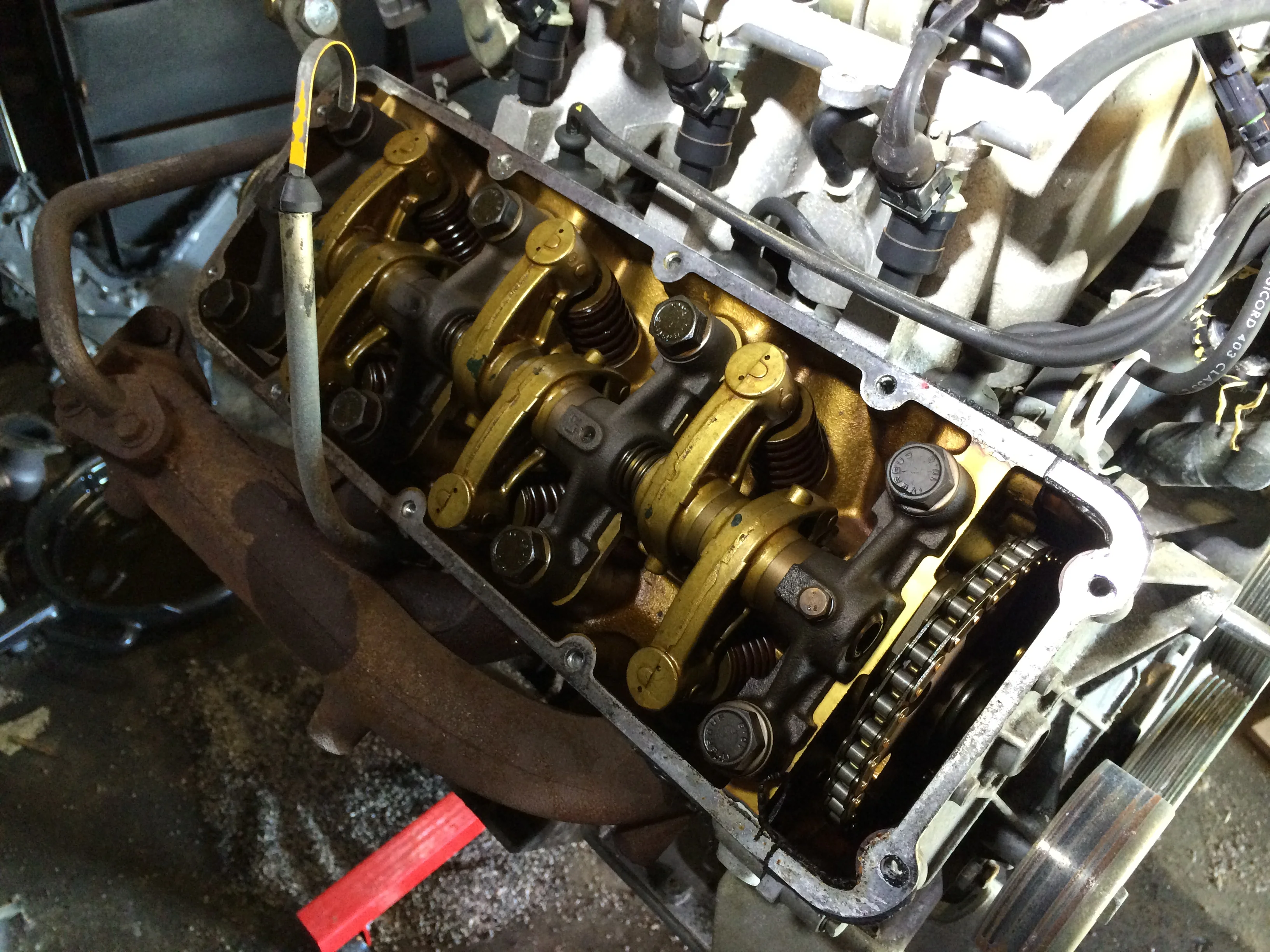
The valve train is revealed once the cylinder heads are removed. The rocker arms have a golden color, while the 2.8L engine has black rocker arms.
Passenger Side Valve Cover
Before removing the bolts from the passenger side valve cover, I decided to remove the distributor cap. There are three (3) bolts that can be removed with a 7mm or 5/6" socket. The cap comes right off. I decided to remove all of the spark plug wires from the engine as well, rather than have the cap ranging the wires.
The three red dots mark the nuts for the distributor cap. These can be removed with a 7mm or 5/6" socket.
The distributor cap removed, revealing the rotor.
On this side of the engine I unbolted the spark plug wire bracket from the cylinder head. This was particularly easy since one of the bolts was missing. They're held on with two bolts.
The cold air temperature sensor's wiring harness is mounted to the back of the cylinder head. The lower two bolts can be removed with a 13mm socket. There are washers on both sides of the mounting plate. To keep from losing them I just screwed them back into the head after the bracket was out.
The cold air temperature sensor is mounted on the back of the head, and can be removed by taking out the two nuts marked in red with a 13mm socket. I had already taking out the valve cover heads before realizing the harness was there.
With the distributor cap and temperature mount out of the way, there are ten (10) bolts that need to be removed with an 11mm socket to release the cover. The four (4) at the front of the head are longer than the five (5) further back. The final bolt is very long bolt, and is on the rear top of the valve cover.
It's probably easier to first remove the cold air intake from the top of the intake manifold. I couldn't find the correctly sized hex wrench, so I left it in place and pushed it aside as best I could to remove the valve cover bolts.
The bolts on the cylinder head can be removed with a 13mm wrench. This also shows the cracked oil filler that I need to replace.
The valve train under the passenger side cylinder head.
Removing the Main Pulley Nut
To remove the timing cover, the main pulley needs to come off. While I had no trouble getting the 2.8L engine's main pulley nut off, this one wound up being far more stubborn. I also placed a piece of wood on the but and gave it a few good whacks with a hammer to let the Kroil seep into the areas revealed by the vibration the impact introduced, and to try to break the locktite free.
I first hit the nut with some Kroil penetrating oil to help with loosening it. I added the oil inside the front of the nut, behind the nut, and behind the pulley itself.
Locking the crank with the flex plate
Since turning the nut will likely turn the engine, I needed to lock the engine. I decide do try what I did on my 2.8L engine: I'd put mount the flex plate to the 3.0L and put a long bolt through it to stop the engine.
The flex plate is surprisingly tricky to mount. There are the two small discs that mount in front of and behind it. The spacing in the hose on these plates, the flex plate and the crank are not equal. It's a small difference -- just enough to make it seem like you just have the alignment a little off. It took me a while to get all the holes lined up properly. I then marked the discs on the plates in case I needed to do it again. I only mounted the flex plate with three bolts, since this was just a temporary fitting, and I only hand-tightened them.
I ran a bolt through one of the torque converter mounting holes in the flex plate, grabbed my 35mm socket and tried to turn the wrench. After failing to do anything, I tried again with a five foot long pipe over the wrench. The nut appeared to turn, but it was an illusion -- I actually broke the 3/8" to 1/2" adaptor on my wrench.
Temporarily mounting the flex plate on the engine so that it can be used to keep the engine from rotating while breaking the main pulley nut free.

Broken 3/8" to 1/2" socket adaptor from trying to break the main pulley nut free.
After grabbing the 1/2" wrench that I should have been using in the first place, I tried again. Once more the nut seemed to be turning, but it wasn't -- this time I was actually bending the flex plate, with the bolt acting as a lever. I think the damage could be hammered back, but I'm not sure I'd trust it afterwards.


Locking the crank with a locking tool
For my next attempt, I obtained a flywheel locking tool made by Billy Chingas (1batt4u on DMCTalk) for $35 USD. It's a well made stainless-steel tool, and comes with the bolt to mount it. The design is based on the original tool provided by DeLorean and Volvo to lock the flywheel to remove the crank nut, enhanced with a second set of teeth on the other side in case the first side is damaged.
After re-attaching the flex plate to the engine, the first thing I discovered was that the tool mounts on the transmission, not the engine. This is obvious from the pictures in his thread and from the Workshop Manual. I was going to try to drill another hole in the center of the tool so that I could use a transmission mounting hole, but I really don't have the tools to do that.
Instead, I hauled the engine back over to the transmission, lined them up and bolted them back together. This was quite a bit easier than I expected. With everything tightened down, I attached the tool on the bottom driver's side of the transmission, fit the tool into the teeth of the flex plate, and tightened it down.
My nut is on tight. I put the wrench on the nut, used my cheater bar for extra leverage, and promptly bent the teeth on the locking tool. I don't think this was a failure of the tool. Stainless is softer than normal steel, and it's better for the tool to fail than for some part of the engine to break.
I tried using the a 250 ft/lb air impact wrench, again locking the flex plate with the other side of the tool. Not that it mattered -- the wimpy impact wrench had no effect, even after running it for a few minutes, including running it forward briefly to try to break the nut free the other way. It should be noted that the manuals say to not use an air impact wrench, but I think with the flywheel locked this isn't much of an issue, and they're more concerned about much stronger wrenches than the one I had.
I tried the wrench-and-cheater-bar again, and promptly bent the remaining teeth on the tool. I ordered a replacement tool from Bill, since I think it is very valuable to have -- it's just not going to help me get this particular nut off.


Cutting off the nut
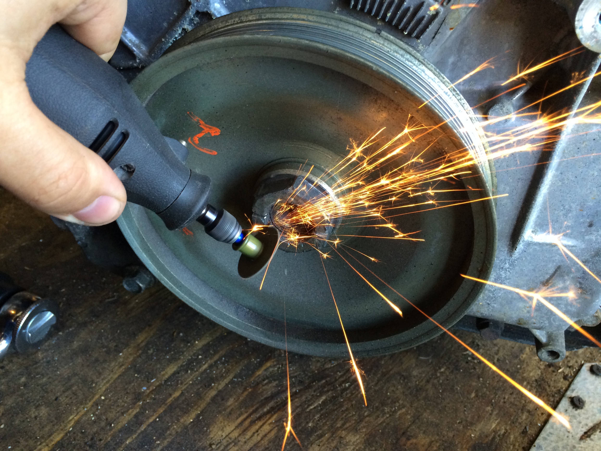
So it's come to this. I finally resorted to removing the nut the way I had a few years ago on my 2.8L engine: a Dremel tool and and some cutting discs. The trick here is to be very, very careful to not cut the threads on the crank, or else you'll be replacing the crank as well. You also don't ned to cut all the way through the nut; if you weaken it enough, it will flex outward and can be spun off the shaft. You also want to make sure to leave enough of the nut that you can still fit a wrench on it.
I used a Dremel and seven Heavy Duty Cut-Off Discs to try to remove the nut. While I was successful a few years ago on my 2.8L engine, I failed this time. I wound up cutting for a couple of hours, trying to weaken the metal enough to break the nut free. Having forgotten my replacement flywheel lock at home, I put a bolt through the damaged flex plate to lock it against the engine to seize the crank, and tried my five foot breaker bar on it, but it still wouldn't budge. I also hit it with my air impact wrench a few times, but to no avail.
I don't recommend trying to cut the nut off, as there is a high risk of damaging the threads on the shaft.


Applying Heat
I finally decided to resort to heating the nut. I was avoiding this because I didn't want to replace the seal in the timing cover, which would likely be damaged by a torch, but I was running out of ideas.
I used my MAP torch (easily and inexpensively available at many hardware stores) to heat the nut; I found warnings against heating the shaft itself, so I tried to stay away from that. After a minute of applying heat, I tried to air impact wrench and then the five foot breaker bar, but it wouldn't move. I applied another two minutes of heat and tried the breaker bar again, and it slowly turned free. Note that the amount of force I used would likely have bent the flywheel lock again, but the bolt in the already-damaged flywheel was able to hold it so I could finally remove the nut.
Removing the Main Pulley
Before attempting to remove the main pulley, make sure the keyway is pointing upward. If it isn't, the key can fall out into the oil pan. My keyway was already pointing mostly upward, so I figured I was good. Otherwise, you'll need to rotate the engine, which is most easily done by putting a new nut on the shaft and rotating it with a wrench. Since you haven't torqued down the nut, it should be easy to get it off again.
With the keyway aligned, you can pop the pulley off with some gentle prying between the timing cover and the back of the pulley. Mine slid off quite easily.
Shaft Thread Damage
I was not nearly as careful as I'd thought I'd been when cutting the nut, and had actually cut into the threads on the shaft more than I'd expected. While they are moderately damaged over about 1/3 of the surface, the rest of the shaft is in good shape. I had done similar damage to the shaft threads on my old 2.8L engine and never had a problem with the nut coming off on its own, so I'm not overly worried about it this time either. I also have no interest in replacing the crank -- it would be easier (and possibly cheaper) to buy another 3.0L engine.


Removing the Distributor
The distributor is mounted on the front of the 3.0L engine. While much easier to get to than on the 2.8L engine, to come off to remove the timing cover. Luckily this is pretty easy.
I had already removed the distributor cap to take off the passenger side valve cover by removing the three (3) bolts with a 7mm or 5/6" socket. Next comes the rotor, which takes a 5mm hex wrench for the three bolts.
With the rotor out of the way, the plastic shield can be removed to reveal two bolts holding the distributor housing to the timing cover. A 13mm socket will take out those bolts.
The last piece is the distributor cam bolt. This requires a 10mm hex wrench and a fair bit of force to break it free. With that out of the way, the remainder of the assembly can be removed from the timing cover.
Other Accessories
One of the idler pulleys was mounted on my timing cover. This came off easily with a 15mm socket.
There is a bracket mounted underneath the driver's side cylinder head that is attached to both the head and the timing cover. This is similar to the air conditioning belt tensioner in on the 2.8L engine. Here, one bolt is pointed upward under the head, one pointing downward into the timing cover, and another on the face of the timing cover. These three bolts are removed with a 13mm socket.
Another bracket is mounted on the bottom of the engine on the driver's side. This has another three bolts, two on the cover and one on the lower crankcase, and is removed with a 15mm socket.
These three bolts (green, 13mm socket) secure a bracket to under the driver's side cylinder head.
Three bolts (green, 15mm socket) hold a bracket to the bottom of the engine.
Removing the Timing Cover
With everything out of the way, the timing cover can finally be unbolted. There are twenty five (25) bolts in three lengths around the perimeter of the cover that need to be removed with a 13mm socket. After that, my cover came off easily, although you may need to pry it off if the gasket is particularly stuck.
The timing cover is held on with 25 bolts (13mm socket) with a mix of bolt lengths.
The timing cover removed, revealing the golden internals of the 3.0L engine.
The next step is to remove the oil pan and lower crankcase.