New Rear KWs and a Rusted Out Trailing Arm
Joe Angell
I made a video detailing the KW installation and replacing the trailing arms with new stainless steel ones from DeLorean Industries.
I’d done the front suspension, so all I had to do now was install the new KWs in the rear and I’d be done. That isn’t quite how it went, though.
Replacing the Passenger Side Shock
The passenger side wasn’t too hard to replace. I had previously installed coil-overs on the rear, and they were probably fine, but I had new KWs so I went about taking them out.
Old Pivot Bolt
This isn’t too involved, but the lower pivot bolt was a bit annoying. I was able to turn it with a wrench, and from there I was able to tap it out with a hammer. The brass hammer was a little slow, so I put the nut back on the bolt and used a four-pound sledgehammer to tap it out the rest of the way.
I replaced the bolt as well. It probably didn’t need it, but it didn’t hurt, and I had been hitting it with a hammer a lot. I made sure to apply plenty of anti-seize in the hopes of making it easier to remove in the future.
Tapping out the old pivot bolt with a brass hammer and a punch.
Old Shock
The nut on top of the shock did not want to come off. There must be some way to hold the shock while you turn the nut that I’m not aware of, because I couldn’t figure it out. I resorted to cutting a vertical slice into the nut with a Dremel cut-off wheel, which loosened it enough that I could remove it with a wrench. I couldn’t just cut the whole thing off like I did with the fronts because the angle grinder won’t fit in there.
The spring still had a little tension on it, but not the “kill you” levels of tension that the original springs can have, but it did drop out of the car fairly quickly when I finally got the top nut off.
Cutting off the nut on top of the shock with a Dremel cut-off disc.
New Coil-OVer
The rear KWs went in basically the same as it does the front. The nuts on top were easy to install. The pivot bolt took a bit of tapping to get through the carrier, and I had to pry the lower link arm up to get the bolt aligned, but it was easy enough. The coil-over slid onto the arm easily. I adjusted the height to roughly where I had it with the old coil-over. Then I torqued the suspension with a jack under the hub carrier to ensure it was properly loaded, and that was it.
Aligning the new pivot bolt in the carrier and lower link arm.
Final installation of the KW coil-over on the passenger side.
Replacing the Driver’s Side Shock
Old Pivot Bolt
Everything here was the same as on the other side. I had to out the nut on top of the shock to remove it, and I had to hammer out the pivot bolt.
The catch was that this pivot bolt was almost nearly seized. I used a 6-foot pipe on the end of my wrench to get it to turn, but it did turn.
If the bolt is seized, you’ll have no choice but to cut the bolt out around the link arm, remove the carrier, and press out the pieces of the bolt. But because it turned, I could use a hammer to very slowly push the pieces out of the arm and carrier.
This also has risks, though. The hub carrier is cast aluminum and can crack, at which point you have to replace the carrier. I’d had this happen on the passenger side when I put those arms in 15 years ago. Luckily, it didn’t break this time.
I knew I was replacing the bolt, so I didn’t bother to put the nut on first. However, all the hammering mushroomed the end of the nut. I had to use an angle grinder to taper it back down so it would fit through the holes in the shock, carrier, and link arm.
Once I was flush with the carrier, I used a punch to push the bolt into the link arm. When the punch was too short, I switched to the old bolt from the passenger side. This worked until the bolt was through the link arm. At that point, the arm shifted so that it was no longer in line with the carrier, and I couldn’t use the old bolt as a pusher anymore. I had some long M10 bolts from another project that worked perfectly as a new punch, before I realized that I could just move the link arm out of the way now and finish tapping the bolt out without the extra fuss.
It took about two hours to get the bolt out. I tried jacking up the link arm, penetrant, and so on. I didn’t try heat, because I didn’t want to ruin the bushing in the link arm. But I did finally get it out.
Hammering out the lower pivot bolt on the driver’s side.
Using another thinner bolt as a punch to get the old bolt out.
New Pivot Bolt
The new bolt was liberally soaked in anti-seize before installation. I once again had trouble aligning the hub carrier and the link arm, but I soon realized that I could use the old bolt as a guide. Since I’d tapered the end with the angle grinder, it would self-center as it was inserted through one end. Then I could feed the new bolt through the other end, and it would push the tapered one out of the way and take its place in the link arm. Nice and simple.
The tapered end of the old bolt, thanks to my angle grinder.
Once the tapered bolt aligned the link arm and hub carrier, I was able to tap the new bolt through, pushing the old bolt out of the way and the new one into the link arm.
New Coil-Over
This went in easy. I did think to unscrew the perch before installing it, which made it easier to line everything up. Otherwise, it was exactly the same as the other side.
Unspooling the perch to make it easier to install the new coil-over.
Nearly completely finished driver’s side coil-over installation.
The Trailing Arms
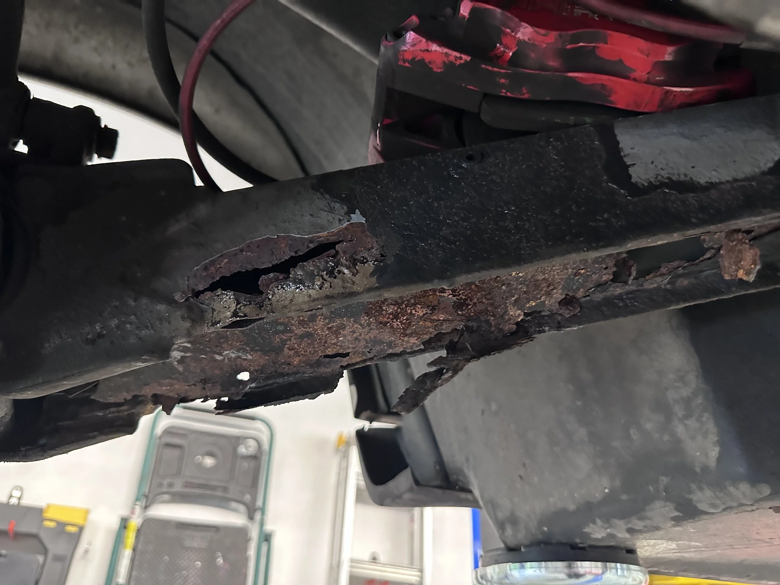
This is where things took a bit of a turn. While I was hammering on the driver’s side pivot bolt, the trailing arm started raining debris onto the floor of my garage. It turns out that the arm was nearly completely ruined before I’d even started. The epoxy and thin remains of metal had been hiding large holes in the arm. The flange that mounted to the hub carrier was nearly snapped off. It was surprising that it hadn’t already failed. Since this holds the rear suspension in line with the body, that would have been bad. I’m not exactly sure how bad, but bad.
The arm didn’t look this bad before the shock of the hammer on the pivot bolt shook all the rust free.
The pile of trailing arm debris from hammering on the pivot bolt.
Another view of the rust. This arm is not serviceable.
Removing the Passenger Side Arm
The main issue with the passenger arm was the brake line. It runs through a flange on the inside of the arm, with the inner brake line held in place through a hex-shaped hole and a nut. The idea is that the brake line should be held in the hole by the hex while you loosen the nut on the other side. The problem is that the hole was rusted out, so it would just spin the entire brake line. After trying penetrant, vice grips, and a screwdriver to hold the nut in the damaged hole, I finally just used a Dremel to cut the nut off the other side. I did nick the threads on the brake line a bit, but not enough to cause any issues with keeping a new nut on.
The bolts holding the arm onto the carrier came off easily, as did the nuts on the trailing arm bolt. I’d long since replaced the bolts themselves with Toby TABs, which are made of Inconel and are much less likely to deform under load. I’m limited on how far back I can shift the TABs back due to the size of the automatic transmission, but that didn’t interfere with removing the arm.
I made sure to keep track of the shims used for toe-in alignment. These are on the TAB between the trailing arm and the frame. I just need to put the right number back on during reassembly.
The back of the flange has a hex-shaped hole to hold the end of the brake line to keep it from turning. It’s rusted out, so it doesn’t work anymore.
Once again, the Dremel saves the day.
Tapping out the carrier bolts for the trailing arm.
Removing the second of the stacked nuts on the trailing arm bolt.
Removing the Driver’s Side Arm
The brake line came off easily on this side, as did all the nuts holding the arm in place. It was a little tricky to maneuver the arm off the car. Disconnecting the parking brake lines helped — they hung down under this arm and limited how much I could shift it. Even so, the transmission limiting the TAB’s range of motion still made it a little tricky to pull the arm off the carrier while also pulling git off the TAB.
Tapping back the TAB to remove the thoroughly rusted trailing arm.
New Stainless Steel Arms
I ordered a pair of new stainless steel trailing arms from DeLorean Industries. These are much sturdier than the original arms and they won’t rust. They also replaced the captured nut design for the brake line with a simple flange. The flange itself is just bolted to the arm, so if you have to take the arm out again you don’t have to drain the brake fluid, which is nice.
The new stainless steel passenger arm next to the old slightly rusted one.
The bolted-on flange for the brake line is much more reliable than the hex-hole brake line holder.
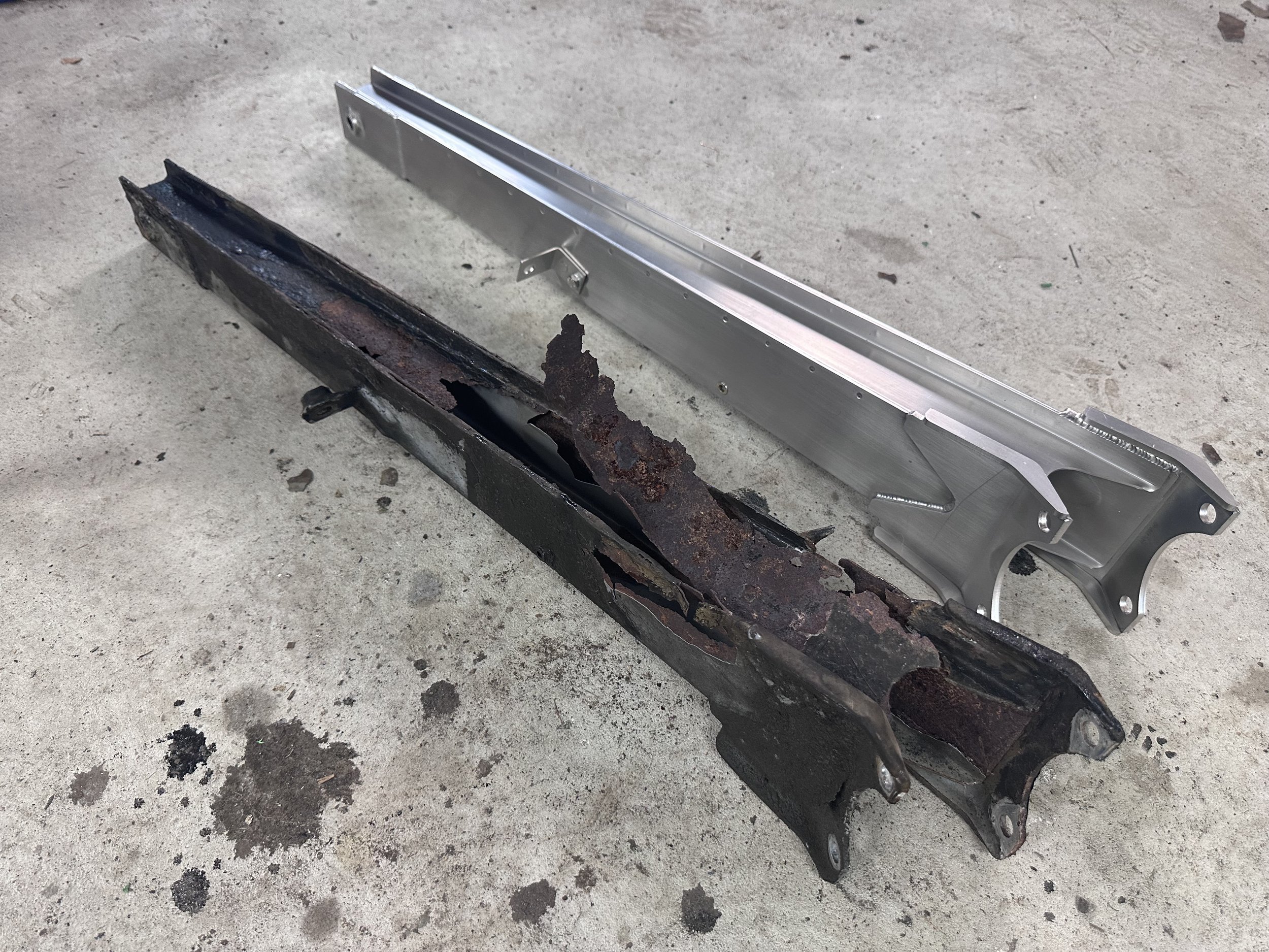
The much worse driver’s side arm and the new stainless arm.
Installing the Passenger Side Arm
This arm was fairly simple — it mounted on the TAB and over the carrier without much trouble. Aligning the bolts on the carrier was the hardest part, and it wasn’t even that hard.
I had to get a new nut to replace the one I’d cut off the brake line. I couldn’t find one that was as thin as the original, but I did find the right threads. The only issue was making sure that the nut was thick enough that the brake line seated completely, which it did.
Mounting the new trailing arm on the hub carrier.
Installing the Driver’s Side Arm
The arm on the driver’s side was trickier. I’m fairly certain that the way you’re supposed to install it is to mount it on the carrier, then insert the TAB through the frame and into the arm. But since the transmission blocked the TAB, I couldn’t do that. What I finally did was to mount the arm on the TAB, then forcibly pry the hub carrier away so that I could fit the trailing arm onto it. This took longer than I’d have liked, but it worked.
First mounting the trailing arm on the TAB…
…before mounting it on the carrier.
The b rake line mounted through the new flange.
The closest nuts I could find where notably thicker than the original brake line nuts.
The gap between the two shows that the brake line is fully seated.
Finishing Up
The last thing to do was re-mount the brakes and bleed the system. This was pretty straightforward. With everything filled, bled, and torqued, I was ready to drive on my new shocks without worrying about my trailing arm failing.