Exhaust Noise, Transmission Leaks, Spark Plugs, IAC Adjustment, and Blower Motor Replacement
Joe Angell
A series of small engine and transmission related needed to be addressed at my next trip to the garage, which spilled over to the garage at my new home.
Exhaust Noise
The exhaust seemed louder on cold starts, but even more than would be expected from the engine being cold. Dave and I took the exhaust apart to apply Permatex Ultra Copper in a further attempt to seal it. This revealed a few of issues.
First, I forgot to put lock washers on the exhaust studs, instead using only flat washers. Many of the nuts had come between a half and a full turn loose. This may well have been causing exhaust leaks at the headers.
The second issue was the passenger side catalytic converted. Overheating the exhaust to the point of glowing a few months back had destroyed the cat, and at some point (during my 500 mile highway test drive, most likely) its contents exited through the exhaust. The cat is now literally an empty pipe. The driver’s side cat is fine, since that was never exposed to such high heat.
The third issue is that these cats weren’t designed to be clamped. Even after slotting the slip joints, the pipe to the muffler could be shifted against the cat.
We solved the first issue with lock washers. No big deal. Just doing that helped with the noise when cold, bringing me to around 78 dBa.
For the second and third issues, the nearby NAPA recommended Jamie’s Performance Muffler Shop for the new cat. He had some even shorter AP 608386 cats for $50 (not sure if they’re 50 state CARB-compliant cats, but whatever) . Even better, he does stainless steel welding for $50/hour. I re-installed my hollowed-out cat and brought the entire car to him, and he replaced the cats, welded them to the pipes and leveled the exhaust. I now had a completely leak-free exhaust.
Jamie went even further. He realized that the dual in/dual out Borla Pro XS exhaust I was using could indeed be run in a more conventional configuration where the exhaust manifold goes to the “top” of the muffler and the tail pipes to the “bottom”. I had been concerned that the hole joining the two chambers wasn’t sufficient, but he was not cornered. He was also able to adjust the pipes to the cats so that they clear the body better, allowing the muffler to be raised up higher than I had it, although the position of my tail pipes means that it still sits lower than stock..
Beyond that, he used much beefier hangers and, thanks to the fact that he could weld easily, got the exhaust properly level. It looks much, much better now.
One other note is that the stainless steel parts I’d used was starting to wear and discolor faster than I’d expected. The DPI headers still looked great, but the pre-bent pipes and the catalytic converters were starting to wear, with both rust and rainbow patterns showing up. The steel hardware on the stainless steel clamps was rusting as well. This was all surface rust, but still disappointing. I did consider that the glowing of passenger side exhaust may have contributed to this, but the driver’s side, which had never gotten that hot, wasn’t much better. Jamie noted that this was a cheaper grade of stainless steel that is more prone to rust. Once this exhaust fails I’ll have him replace my previosly-purchased pipes with higher-grade components so that it doesn’t happen again.
This used to be a catalytic converter. Now it’s just a pipe.
Rainbows showing up in the stainless steel pipes.
Surprisingly rapid rusting of the stainless steel components after only a month on the road.
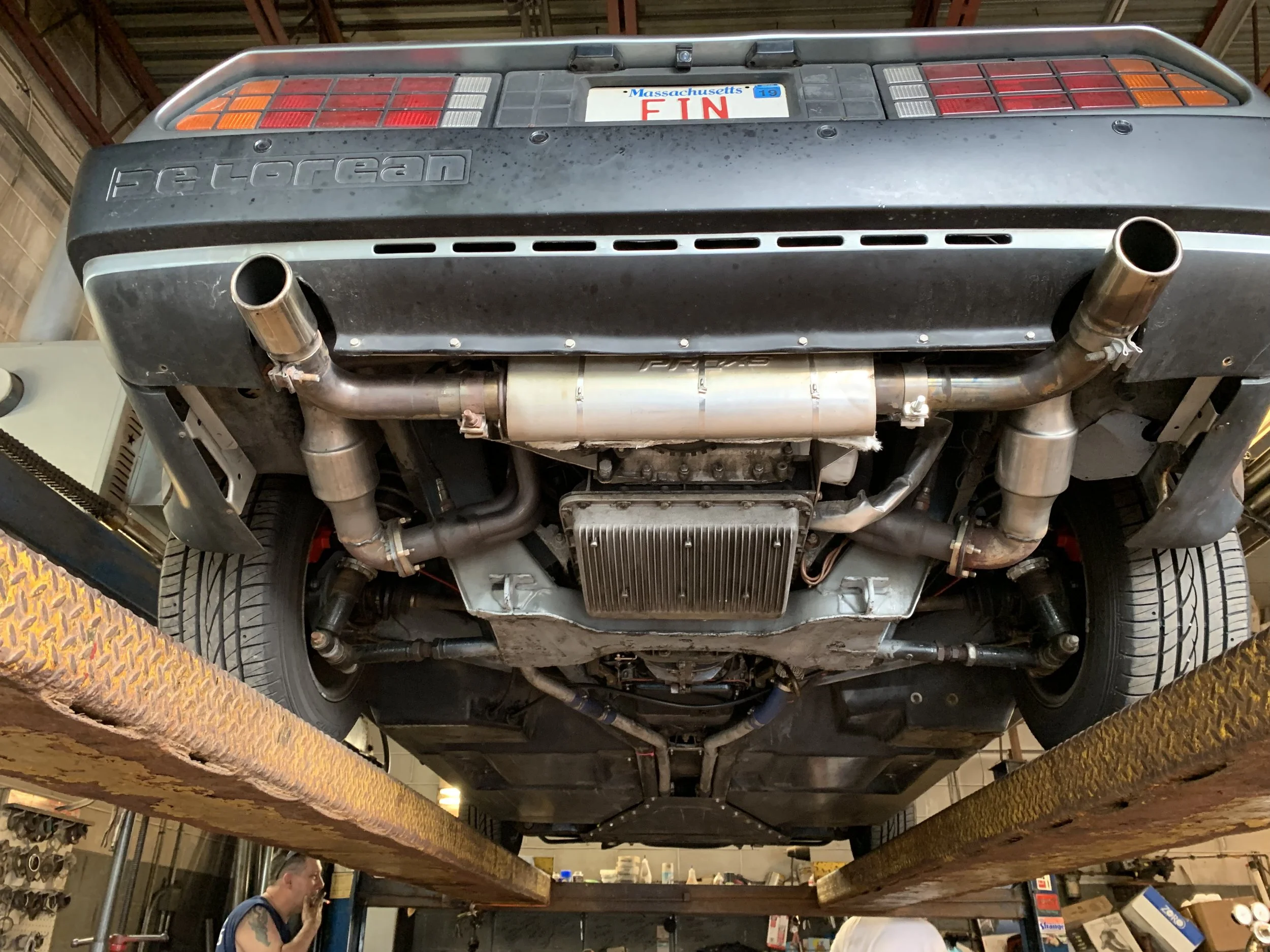
The exhaust being re-installed with new cats.
The final installation, sitting much better and with more conventional routing.
Transmission Leaks
Cooler
We found two transmission leaks. The first was at the transmission cooler . This took a while to figure out. The nut needed to be tightened a little more going on there, and we got the cooler connection as tight as we could, but it kept leaking. We then removed the cooler hose and re-attached it, tightening it has hard as possible, and that seemed to fix it. It seems it was just slightly misaligned, and that was causing the puddle of transmission fluid under the car.
But later I noticed there was still fluid dripping down. Eventually I realized that it wasn’t that nut — it was the connection at the top of the cooler. This leak was masked by the PJ Grady heat sink that was installed over the cooler pipe, as the fluid was running between the heat sink and the pipe and collecting around the lower nut. Tightening the upper nut finally fixed the problem.
The leak at the transmission cooler nut. It was also leaking from the upper nut, running behind the heat sink and tripping off of the bottom nut. These were fixed by tightening both nuts further.
Dipstick
The second was on the transmission dipstick. I had forgotten to attach it to the back fo the cylinder head, which meant that it was rubbing against the axle. This had just started to war a hole though the tube, and fluid was seeping out.
We removed the tube, not realizing that there was about a quart of fluid above the hight of the base of the tube, and promptly spilled it all over the floor. After cleaning that up, we repaired it with some JB Weld epoxy. It’s not a high-temperature or pressurized component, so this is more then adequate to keep it from leaking further. We then properly mounted the dipstick to the transmission and cylinder head to keep this from happening again.
Actually re-installing the dipstick tube was another story. We tried using an O-ring with RTV, but it didn’t work at all — it leaked quite a lot of fluid simply by trying to fill the transmission. I installed did the recommended solution of buying a new otterstat gasket (part 106959). The otterstat and the transmission dipstick tube are exactly the same size, and the gasket is much more robust than the O-ring. I installed that dry, and no more leaks from the tube.
The dipstick tube was attached to the back of the cylinder head with a slotted L-bracket from NAPA, part 11133. A 10mm bolt, nut, and a couple of washers completed the installation. The dipstick tube doesn’t quite sit vertical, but I don’t think it ever did.
However, it still leaked. The tube simply didn’t clear the body properly, which is why it had to be tilted tin the transmission. Since this kept it from sealing, it would dump a quart of fluid on the ground when the car was off. I eventually fixed this by removing the tube and bending it more by wedging it under my vice’s jaws and pulling on it. This allowed it to both sit vertically in the transmission and clear the body. I used a 4” bracket from Lowe’s in place of the shorter NAPA bracket to secure it to the back of the engine.
At one point I dropped the otterstat gasket into the hole int he transmission. I had to drop the pan to fix it. Luckily I had a reusable silicone gasket from DPI, although this time we used RTV to help reduce the chance of it leaking, and made sure not to over tighten the bolts. This worked, and the transmission no longer leaked — at least not at the dipstick or the pan.
The dipstick tube sitting on top of the axle. You can also see the bracket that is supposed to be mounted tot he cylinder he’d resting on the bend in the tube.
Transmission fluid pouring out from the base of the dipstick tube when just using an O-ring and RTV. An otterstat gasket worked much better.
NAPA 11133 slotted L bracket used for mounting the dipstick tube.
The dipstick tube mounted to the L bracket by means of a 10mm bolt, nut, and a large fender washer.
The slightly tilted but non-leaking dipstick tube, with otterstat gasket installed.
Output Flange
And then I found a third leak. I kept seeing fluid collecting on the Hall sensor I had installed for an eventual digital speedometer. This was mounted on the “key” that locks the adjustment ring near the axle. I thought it was automatic transmission fluid, but I couldn’t figure out how the fluid would get there, since this was the final drive. I added dye to the transmission fluid and found that even this area glowed up under UV light. Later I discovered that this is because the gear oil used in the final drive naturally glows under UV light.
The leak wound up being the lip seal on the output flange. Replacing this isn’t super hard, but it can be a bit of a pain. DeLoean Go sells a complete kit (K104216) that includes everything you need for this job. I also got a complete set of cap screws to replace the bolts for the axles, as they are much easier to get on and off than the original bolts.
Before you start, drain the final drive. On a manual I believe you’re draining the entire transmission here, as it’s just one cavity with one fluid, but I have an automatic, so I have a separate fluid just for this. Both the fill and drain plugs uses the same 8mm square drive as the oil pan and transmission pan. Remove the fill plug first — you don’t want to drain it and then find out that you can’t fill it again because the plug is stuck.. This plug is on the driver’s side of the transmission, above and forwards of the output shaft. After that you can remove the drain plug on the bottom of the final drive.
While the fluid drains you can remove the axle. You have to use an open-end wrench turning about 1/6 of a turn each time until the nut is loose enough to remove by hand. I only undid the transmission side of the axle, then pushed it aside.
The output flange comes out next. First, mark the flange so that you know which side is which when re-installing it on the splines. This is held in with a roll pin (or split pin). This is a rolled piece of metal that is a slightly larger diameter than the hole it sits in. This design exerts outwards pressure and locks the flange into place, like a spring. The issue here is that the flange will fit on the shaft fit both ways, but the hole only exactly aligns one way, and if you put it on the wrong way you won’t be able to figure out why the pin doesn’t go back in.
To remove the pin, you need to use a 6mm punch, although a 5mm will work — just don’t use one so small that it slides into the pin instead of pushing on the rim of it. Make absolutely sure that you have the flange rotated such that the pin won’t get wedge against the transmission after you tap it out, or you’re going to have a very hard time getting it back in again.
With the pin out, you should be able to simply pull the flange off. My flange was still in very good shape, and needed no other servicing. Some flanges may have groves in them. The quick test is if your fingernail catches on a groove; if it does, you either need to replace the flange or cap it with stainless steel sleeves to renew it. Both are available from DeLorean vendors, but are not included in the DeLorean Go kit.
My lip seal was tilted, which was probably the source of my leak. I probably could have tapped it back in and been done with it, but I replaced it. To pull it out, I used a hook-shaped pick and pulled it, careful not to scratch the shaft or damage anything else.
Also remove the O-ring that is on the shaft. Replace it immediately with a new one so that you don’t forget to do it later.
I opted for the triple-lip seal from DeLorean Go. It was a few bucks more, but I don’t want to do this again if I can avoid it. Some people advice greasing the seal before re-installing it, but this isn’t strictly necessary. I just tapped mine in. The trick is tapping it in evenly. I bought a 1 1/4” PVC adaptor from the hardware store that fit perfectly in the lip seal, pressing against the encased metal ring of the seal. This allowed me to tap it in with a mallet evenly without damaging the seal. The spring side goes towards the inside of the transmission.
There is another large O-ring that the kit comes with. I didn’t have to replace this, so I won’t go into that here. To do this, you may have to rotate the large ridged nut. It is highly advisable that you do not do this, as it tensions the differential. If you need to do it, make the nut and the transmission case, remove the nut and the “key” that locks it in place, and count the exact number of turns you make. You do not have to completely remove the nut to replace the O-ring, so don’t. Be sure you put the nut back exactly as you found it. If you screw this up, you’ll have to pull the transmission and take apart the final drive to fix the tensioning.
The DeLorean Go kit comes with new roll pins as well. Make sure the slot in the pin is pointed outward. If you don’t, oil can creep up the splines and leak out through the slot in the pin. I also failed to mark my flange, and spent far too much time trying to get the pin past the flange and into the shaft. I went so far as to grind the end of the pin so that it was tapered and would be easier to find the hole in the shaft. Eventually I flipped the flange and the pin went in much easier, although it was still a fair bit of work. It took a few minutes of pounding to get the pin fully seated. This probably took me the most time out of the entire repair.
Before filling, I re-installed the axle using the new hex cap screws. This is a lot easier than the hex head bolts.
Filling is a little tricky. First, you want the car to be level, which means jacking up the front of the car as well. I went a bit risky here and had the front of the car held up only with a floor jack. You should really use use jack stands for safety, but I was not going to be near the front of the car, the rear wheels were on pallets, I wasn’t going to be torquing anything, and if it fell I would be safely behind the car.
To actually fill it you’ll want a long piece of hose. You’ll run this into the hole in the car, then up through the engine compartment and to your bottle of fluid. Slide it onto the top of the bottle, flip it over, and it should start to drain. However, the fluid is pretty thick, and soon the suction from the back of the bottle will keep the fluid from flowing. The simplest thing to do here is to drill a hole in the bottom of the bottle to remove the vacuum. Of course, now you can’t put the bottle down until it’s empty, as there are holes in both ends. I was able to prop the bottle between the engine cover and my garage door.
The fill line is the bottom of the fill hole. This is why the car needs to be level — you need to make sure that the fluid is filled to the bottom of that hole, and I don’t know where the centerline is when the car is tilted. I used two one-quart bottles of fluid, knowing that the excess would leak out of the hole and result in the correct level.
The last step is to re-install the fill plug and lower the car, and you should be good to go. I thought I had another leak afterward, but this wound up just being old fluid dripping off of the transmission case, and it went away after a few drives.
After unbolting the axle, the roll pin has to be tapped out with a 6 mm punch. Make sure the flange is rotated so that the pin won’t get stuck against the transmission case once it is mostly tapped out.
The shaft after removing the flange. The old lip seal can be seen around the shaft, slightly tilted.
Using a pick to slide the O-ring off of the shaft.
My flange had very light marks on the surface, nothing significant enough to require sleeving.
The new triple lip seal(left) and the original seal (right).
The new triple lip seal(left) and the original seal (right).
Sourcing a piece of PVC pipe as a guide for tapping the seal into the transmission.
The new seal installed in the transmission.
The new roll pin after tapering the end to make it a little easier to fit into the flange.
Installing the new cap screws in place of the old hex bolts on the axle.
The 80W gear oil I used for the final drive. This is a lighter green color (left, top) than the brown oil that was in there before (right)
How I got the fluid into the final drive, after drilling a hole in the bottom of the upside-down bottle.
The other end of the hose runs into the fill hole in the final drive.
After filling, excess oil drains out of the hole. The fill level is at the bottom of the hole, so once it stops dripping, it’s full.
Tuning
Dave and I also did some tuning, where he drove and I tinkered with the laptop. This was barely necessary - -the car runs exceptionally well, and the AFR was very close in the majority of the cells. I only had to do minor tweaks at the top end, the bottom end, and just a few cells in the middle.
We also tried advanced acceleration enrichment briefly, but I honestly had no idea how to adjust that, so I went back to simple enrichment again. Maybe I’ll give it another shot in the future.
We also played with off-the-line ignition timing. We actually did get more power out of it by boosting the timing to 20 degrees in the <1200 RPM and >50 MAP corner of the table, although we now get some gurgling from the exhaust off the line. We turned it back down to remove most of the gurgling.
Idle Air Controller Adjustments
I also noticed that the car would start idling high after a bit of driving, going up to 1200 RPM. I closed the throttle all the way so that I could reply solely on the stepper motor to control idle, but the stepper was completely closed already. Curiously, turning the car off and on again brought the idle back down, and the stepper reset to about 30 steps. This suggests that it’s not a vacuum leak, as that would be more constant. Dave thinks it could be that the stepper is getting stuck, which isn’t unreasonable — when the car restarts, the motor would move to a more open position, then close again as it comes down to idle.
After firing the pintle off a few more times while testing the IAC’s moment, I decided to do this properly: I removed the throttle body and separated it from the IAC housing, then mounted the IAC into the housing. The housing requires security bits (torx but with a hole in the center, but I had a complete set of security bits that included this) This is what I should have done in the first place — I could see the full range of the IAC movement.
As TunerStudio’s test mode panel notes, you should extend the IAC beyond its maximum range for its home position, then back in for the run position. The home steps should be greater than the run steps, as you want the motor to go out so far that it seals off the bypass completely and then tries to run further than that. From there, it will run backwards to open the bypass and let air in. If you don’t have the home steps set up correctly, the MegaSquirt won’t be able to find home properly, and you might wind up having the IAC open a bit too much. That’s what was happening to me.
Once re-installed, the IAC now reported about 30-40 steps when warmed up at idle with the throttle screw adjusted so that the throttle was completely closed. I’ll likely need to adjust the closed loop IAC table to account for the changes, but hopefully I’ve fixed my high idle problem.
I managed to break one of the IAC mounting screws when re-installing it (don’t over tighten, kids), but the remaining three are more than enough to keep it tight to the throttle, and I can always remove the IAC housing and the remains of the screw if I do find I have a vacuum leak, but I doubt it’ll be an issue.
The IAC in the “run” position, allowing air through the bypass and into the engine.
The IAC in the “home” position, completely sealing off the bypass. Note that you should set the number of home steps so that the motor is pushing too far into the hole so that it is guaranteed to find home, as opposed to trying to find the number of steps that exactly seals it.
Spark Plug Wires
Dave noticed that I didn't have matching spark plug wires. This was true — I’d pulled a few sets from other EDIS-based vehicles from the junkyard, picked the ones with the best lengths and installed them. What I didn’t do was check to see if they were any good.
We found that the resistance ranged from 6k ohms to 13 k ohms, with one being 3k ohms. Wires do increase resistance the longer they are, but I had the luxury of being able to choose the best from a series of wires.
I went to the junkyard and bought 18 more wires of various lengths for around $15 total. I tested each with a multimeter, sorting them by resistance. I then used the ~7k ohm ones, which had enough length variation to reach the far side of the engine without a lot of extra slack on the near side. After swapping out the boots, they easily popped back into the engine and it fired right up. I took some of the wire clips from the junkyard, and used them to better organize the wires. While I was replacing the wires, I also removed the Champion spark plugs and put back in the higher-quality Bosch ones.
Part of the hope of using these new wires and plugs was to fix the vibration problem I was having. It felt a little better, but I can’t be sure just yet. I’ll have to do some more tests once I’m driving again.
All the wires sorted by resistance, from low (left) to high (right).
The new wires routed through the engine bay.
Broken Crankcase Vent Thing
At one point I found a crecent-shaped piece of plastic on the floor. It appeared to have broken off of the thing that sits in the crankcase vent hole on the driver’s side cylinder head. Unlike most broken parts, this was surprisingly easy to repair, almost holding itself back together. I mixed up some two-part JB Weld epoxy to make it permanent. A small thing, and an easy fix.
The repaired vent thing, clamped while the epoxy dries.
Blower Motor Failure
Around this time, my blower motor started making loud screeching noises. One of the bearings had failed — you could even hear it after taking it out of the car. I got a replacement 35582 from Advanced Auto, after AutoZone and O’Reily’s couldn’t find one quickly enough. It was around $30.
The “squirrel cage” fan has to be transferred from the old motor to the new one, which wasn’t a problem. Just don’t forget the washer/spacer that sites on the shaft under the cage. The ground plug also has to be moved to the new motor, as well as the vent tube, which must be re-attached to keep the motor from overheating.
I had some trouble mounting the new motor, though. My first attempts resulted in the cage rubbing against the box that the motor mounts in. I was finally able to shift it around enough that it didn’t rub, then torque down the bolts to keep it secured. The new motor blows fine and doesn’t make any noise.
The motor ready to be replaced.
The old motor with its cage removed, and the two wrenches needed for the job.
The washer/spacer installed on the shaft to support the squirrel cage.
The label of the motor with its model number and an arrow indicating the direction of rotation..
The installed motor.
The label of the new blower motor, for reference.