Steering Rack, Shaft and Bushing Replacement
Joe Angell
I had a weird vibration from the front left of my car. I never could figure it out, but I had some old parts that I decided I should replace. One of those was the steering rack. It actually isn’t too bad, but a boot had torn and gotten a lot of grime in it, so I decided that I’d swap it out, and the new ones from DMC aren’t too terribly expensive. I did the ball joints while I was there as well, and the steering bushing that goes through the firewall. And why not do a vibration-dampening single-piece steering shaft while I’m at it.
As an Amazon Associate, I earn from qualifying purchases (learn more here), so if you want to support me, that’s a good way to do it.
Removing the Old Steering Rack
To start, I got the car up on the left and removed the front tires. I then emptied out the trunk over the driver’s side and pulled the brake reservoir cover. This provides extra access to the top of the steering rack and the steering shaft.
To pull the rack, you first have to disconnect the steering shaft. I had forgotten that I’d already update the shaft to a single-piece unit over a decade ago, but I didn’t have a vibration-dampening U-joint yet, so I did another upgrade.
The U-joints I had each use two sets at 90-degree angles to each other that are removed with a 10mm allen wrench. You have to turn the shaft to access the screws. Once loose, I could slide the shaft out and remove the U-joint itself. This wound up being a bit of a pain, especially since the top U-joint isn’t too easy to get to, but I did eventually it them loose and pull it from the car, along with the steering shaft.. The lower joint was pretty well stuck on the splines, though. We dealt with that later.
The lower aftermarket U-joint . The arrow points to a mostly-removed set screw.
The upper U-joint.
Next, the tie rod ends have to be popped off of the hub. I had a pair of M8 nuts locking the tie rod ends in place, although a single nylock on each side is more common. These need a 16mm socket. You then use a pickle fork to separate the ball joints from the hub, tapping it with a hammer to release it, or an air tool version of the same. My non-air-tool pickle fork was far too large, but it still worked well enough to get the ball joints free.
The rack itself is held to the frame by four M8 nylocks and their washers, which are accessible from holes under the front frame extension. Each pair of nylocks secures a bracket and its bushing, and are removed with a 13mm socket.
The brackets are “U” shaped, and both hold down the rack and keep it centered in the front frame extension. The driver and passenger side brackets are different — round on the driver’s side and square on the passenger side, and has a separate plate on the bottom — and require different bushings. It’s worth noting that while bushings are available from DeLorean vendors, the brackets themselves are not, so you’ll need to clean up and reuse your existing brackets. Use a wrench, not an impact gun, or you can accidentally pull the pressed-in stud sof the brackets themselves.
The bushings are split, so once you get the nuts off and the brackets out, you can pry the bushings apart and remove them from the rack.
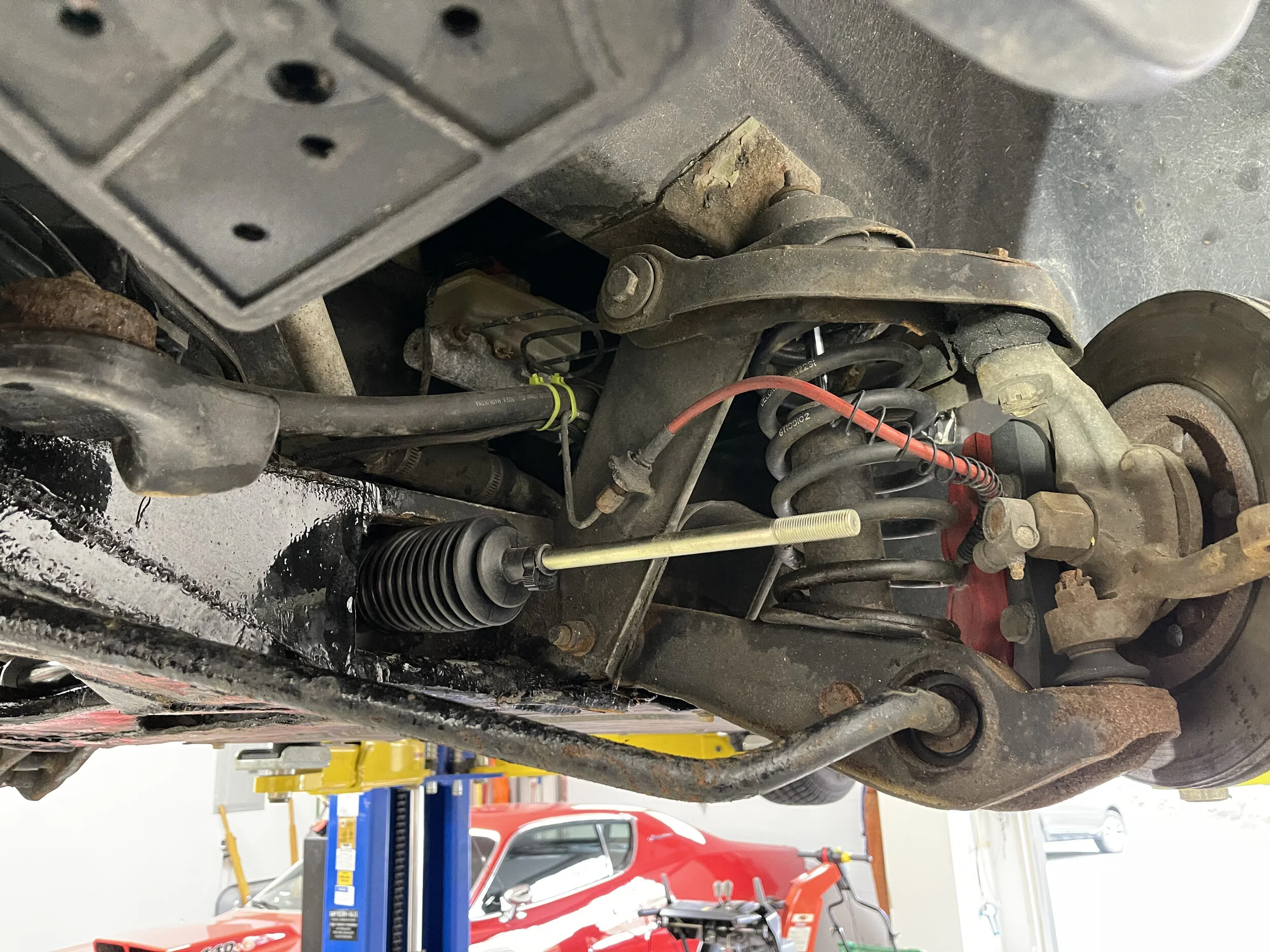
The yellow arrows point to the access holes for the bracket nuts. The blue arrow indicates the disconnected tie rod end.
The driver’s side bushing is visible from under the car.
The driver’s side bracket (left), passenger bracket (right), and the plate that sits under the passenger bracket.
My lower U-joint was firmly stuck on the splines of the rack. You need to remove it to get the rack out. After failing to break it free by hand, my friend switched to a MAP torch, being careful to keep the heat on the joint and away from the A/C, coolant, and brake lines in the vicinity. After a bit of smoking, we were able to pry it off.
The rack then has to be rotated counterclockwise to get it to slide out from the driver’s side. We used a long pry bar to help orient it properly. Removing the tie rod ends first makes it easier to take it out.
Using a MAP torch, visible near the top of the picture, to heat up the lower U-Joint. The blue flame is slightly visible here.
Using a pro bar to rotate the rack so it can be removed from the front frame extension.
We tried to count the number of turns for the tie rod ends, then installed the new ends onto the new rack roughly the same amount. That got us close enough until I could get a proper alignment done.
The rack goes back in the same way it came out. This sounds easy, but I remember it taking us quite a bit of time. The instructions that come with the rack help a lot here. The most important thing was to make sure that the rack was properly situated in the frame. The bushings and brackets horizontally position the rack, especially the passenger side one with its bottom plate. There are specific notes in the instructions about using a pry bar to fit things and to get the rack rotated properly into position. I’d detail some here, but it’s been too long between when I wrote this entry and did the swap, so I’m afraid all I can say is to look at the docs.
The instructions have some helpful hints. Install the passenger side bushing first, and make sure the bracket properly seats on the retaining plate as you put it through the frame holes. Don’t tighten it down yet. Next, you have to rotate the rack so that you can fit the driver’s side bushing in the available space, using a pry bar to maneuver the bushing into position, but once it’s clamped on you can rotate the rack upright again. Liberal use of a lubricant like WD-40 is recommended. You can now secure the brackets with nylocks, being careful not to over-tighten them.
The rack inside the frame, but not yet oriented or secured.

The brackets (top), their old bushings (middle), and the new bushings (bottom).
The brackets after being cleaned up as best I could with a wire wheel on a power drill.
The new bushing installed on the passenger side, but not yet locked in place with the bracket.
The driver side bushing positioned but not secured with the bracket yet.
The driver side bushing and bracket, in its final position.
New nylocks installed on the tie rod ends.
Steering Bushing
My steering bushing was cracked apart, so we replaced that as well. The DMC bushing bushing comes with very helpful instructions, although in the end I installed a polyurethane bushing instead.
I did not read the instructions, at least not initially. It seems you only have to undo the tilt/slide adjustment knob on the steering wheel and slide the entire thing back towards the seat. I elected to remove the entire steering column. Admittedly, this did make the bushing installation easier, since I didn’t have the column in the way, and I don’t think it was much harder to take out the wheel.
To do it the way I did it, you remove the two bolts that hold the shaft in place. Since this involves lying on your back in under the dash, it’s a lot easier if you take the driver’s side kneepads out. You also have to disconnect three electrical connectors from the steering column harness.
Once that’s done (and the upper U-joint is removed, which mine was already as part of replacing shaft and U-joints), you can “just” pull the entire column towards you from the driver’s seat and remove it from the car.
The bushing itself is pressed into the firewall. The old one was cracked and came out easily, but the new one is very hard to get back in, so you need to build a simple tool. This is where you really want to read the instructions. The components of the tool are:
3” long 10mm bolt
10mm nut
2 washers (I used four)
1 3/8” socket
First, put the washer on the bolt, and then slide the socket onto the bolt., with the open side opposite of the washer, and then run the end of the bolt through the firewall. The socket is there to create a ring-shaped surface for the bushing to push against as it is pressed through the firewall, and to keep the firewall itself from breaking under the strain. Without that socket, you will crack the firewall and make a bigger hole, which is not what you want.
Cover the bushing in the provided lubricant, and then slide it over the bolt from the inside of the car with the flat side facing the cabin. Next, add a washer and the nut, and snug it against the bushing. Make sure the bushing is as centered as you can get it.
At this point you need someone outside the car and someone else inside it. The outside person uses a socket wrench to compress the tool together, pushing the bushing into the firewall. The person inside uses a box wrench to keep the nut from spinning.
You’ll eventually hear a snap as the bushing pops into place. It should be flat against the firewall. You can now disassemble the tool and put everything back together.
The steering assembly after being removed from the car.
The new bushing (left) and the old, cracked bushing (right).
The “tool” built to push the bushing in, in the order they are stacked in: a bolt, two washers, the bushing itself, two more washers, a socket, and a nut. The socket is part of the tool.
The final installed bushing.
After we got the column out, we noticed that the crumple cage was broken. I used my new electric welding gear to spot weld some repairs to the cage before we put it back in the car.

The broken cage.
The repaired cage.
In my case, the column came out without the lower part of the shaft, but they are designed as separate pieces and just slide back together.
It was really hard to get the shaft back in through the new bushing, though. We greased the inside of the bushing, got the column in place, and then braced a piece of wood along the top and hit it with a small sledgehammer until it finally seated properly.
Dave positioning a piece of 2x4 so that we could tap the shaft back through the new bushing.
Once through the firewall, the shaft can be reconnected to the U-joint and. Don’t forget to reconnect the three connectors under the dash, and make sure they’re snug — I had a random engine shutoff that took weeks to diagnose before I realized I just didn’t plug the ignition connector in firmly enough.
Make sure that you have the wheel as straight as possible when you attach the upper U-joint to the upper shaft, or your wheel won’t be straight. We thought we had it straight, but not quite, and we didn’t realize it until everything was back together.
Being lazy, I decided to just remove the wheel and realign that. This isn’t ideal, since the steering lock will be misaligned, but I don’t care that much about that. Maybe I’ll fix it in the future someday.
To pull the wheel off, I got a steering wheel and gear puller from Amazon. Unfortunately, I bought one that was too large, and I couldn’t get both bolts into the steering wheel holes. I wound up using only one bolt, which worked, although it bent the hell out of the bolt. Another trick is to use an air chisel to force it off, placing it between the back of the wheel and the shaft, but I didn’t have one of those. A hammer on the back of the wheel didn’t work for me either, and simply pulling by hand did nothing at all.
Speaking of bolts, you need 4” long 1/4”-28 bolts, and not M6 bolts, to pull the wheel. M6 bolts will just ruin the threads in the holes. 1/4'“-28. 4” long seemed to work for me Remember to loosen the big nut on the wheel, but don’t remove it until you have the wheel free, unless you want to hit yourself in the face with the wheel.
The steering wheel wasn’t quite straight after we replaced the bushing.
The steering wheel/gear puller I used, and the one 1/4”-28 bolt that I belt pulling it out.
Single Piece Steering Shaft
There are some detailed instructions for a single-piece Borgeson vibration-dampening steering shaft by dn010 on DMCTalk.org, which I followed for my installation. I highly recommend reading this. It also shows the original steering shaft and describes how to remove it. DeLorean vendors also sell a kit version of this that’s a little more expensive, but includes all the same parts so you don’t have to source them yourself.
If you do want to do it yourself, the single-piece shaft requires three new parts, which together cost under $200, and are available from Amazon:
This design uses a "double D” style shaft and joints that accept that style. The old single-piece setup I had used splines. The “double D” should be a lot easier to remove than the splines in the future. You can also cut the shaft to the correct length, which was not possible with the splined one, as the splines were only on the end.
The lower U-joint is the vibration-dampening one. It is longer than the upper one to house the rubber dampener.
As with my old U-joints, these new ones use a pair of set screws to attach to the rack and upper steering shaft, but also another pair for the lower shaft. The shaft has to be cut down rom 18” to 11.5” with a hack saw, although I’m lazy and used an angle grinder instead. I marked the place to cut with a paint marker.
To make sure the shaft didn’t slip, I followed dn010’s advice and drilled some depressions into the basic with my simple drill press. The set screws would rest in these detents to and ensure that the shaft doesn’t slip in or out of the U-joint at all. To figure out where to drill, I pushed the shaft into the U-joint, tightened one of the set screws, and used a paint marker to mark through the hole for the other set screw. I then repeated the process for the other hole, and for the other U-joint.
The new single-piece shaft and U-joints (top) and the old single-piece shaft and joints (bottom).
Drilling the detents into the shaft.
Pinion Core Swap
DeLorean Texas requires a core swap of the pinion gear from the original rack, and the rack includes instructions explaining how to do this.. However, my rack had already been replaced with one from DeLorean Texas about 15 years ago, and it did not have an accessible pinion gear. After contacting DeLorean and sending them pictures of my old rack, they waived the core requirement and refunded me the core charge. Nice and easy.
My old DeLorean Texas steering rack. This is not the kind you can pull the pinion from.