Digital Speedometer
Joe Angell
UPDATE December 2022: I’ve made a video that covers the speedometer system, my problems with it, and the solution I came up with. Like and subscribe and stuff.
For years now I have not had a working speedometer. For those who don’t know, the DeLorean speedometer train runs from the front left wheel, starting with the angle drive. This does a 90 degree turn into the lower speedometer cable, through the firewall and into the bottom of the LAMBDA counter (whose sole purpose is to tell you that it’s time to replace the oxygen sensor after a certain number of miles by turning on the LAMBDA light in the instrument cluster). The user speedometer cable exits the top of the LAMBDA counter and goes into the speedometer.
In my car, this entire chain works perfectly fine in pieces, turning easily and smoothly, but once you put everything together and mount it in the car, the angle drive breaks within five miles. After a few angle drives, I just gave up on it.
More recently I decided to build a digital speedometer. Eventually I’ll have a custom digital instrument cluster, but for now I just wanted to see the speed. I had done some research in the past, and had intended to use evenly-spaced magnets on a rear axle, and a hall sensor mounted nearby that would read the passing magnets. I would buy a simple Hall effect sensor component and build the enclosures and mountings myself. Luckily, someone else had solved the hardware problem in a much better way.
Sensor Hardware
This thread on DMCTalk provides the perfect sensor hardware. The axles on the DeLorean are fairly standard, meaning that a Porsche 930 VSS ring will mount directly beneath the bolts that hold the axle to the transmission. The ring has 16 teeth, which allows for fairly fine speed sensing. You can easily find these with a simple google search, and they cost around $20.
The second step is the Hall sensor. The same thread mentions a 55505 unit, which is completely enclosed, runs on 5v, and is ready to mount. These are again available for under $20.
To mount the ring, I cut it in half between the teeth, then attached it to the axle using the existing mounting bolts. For the sensor, I used a slotted “L” shaped bracket purchased from NAPA, part 11133. I reused the bolt for differential adjustment lock. If you do this, be very careful not to lose the “key” that locks the adjustment ring in place, and not to rotate the ring itself.
I extended the Hall sensor pigtail with new wires. Later I replaced these with a shielded cable to reduce noise, which would manifest as random spikes in speed. I used the existing hole in the firewall for the old oxygen sensor to get the wires into the cabin.
NAPA 11133 slotted “L” bracket for mounting the Hall sensor.
The Porsche 930 VSS ring and Hall sensor mounted to the transmission.
Electronics
For the electronics I made use of parts I mostly already had lying around. The display is an Adafruit four digit seven segment LED backpack and matching LED display. I had both blue and white displays on hand. I started with the white one, but it washed out too much in sunlight and switched to the blue.
The Adafruit backpack is easy to wire thanks to it being an I2C device. It just needs two wires for power and two wires for I2C communication.
The hardware responsible for driving the display and monitoring the Hall sensor is an Arduino. I used a Mega 2560, which is overkill for this (an Uno is fine), but I will be expanding this to other projects and wanted the extra pins for future use.
I also bought a cheap 12v to 5v buck power supply from Amazon. This is used to power the Arduino from the car’s electrical system when the accessory relay is on.
The wiring is very simple:
Hall sensor: 5v and ground from the Arduino or buck power supply, with the remaining wire going to an interrupt pin on the Arduino.
Display: 5v and ground from the buck power supply, plus clock and communication wires from the Arduino.
Arduino power; 5v and ground from the buck power supply.
Inside the car, the Arduino is wired to the the accessory relay through a second fuse box I have behind the driver’s seat. It had an as-yet-unused fuse slot for the buck power supply, so I made use of that.
For testing purposes, I ran the wires from the Hall sensor and the fuse box along the passenger side of the center console. I added some simple connectors commonly used for LED light strips so that I could easily disconnect the various components as needed. I soldered jumper pins onto the end of the wires to connect them to the Arduino. While I eventually plan to build a plastic case for the Arduino, at the moment it is sitting in its cut-up cardboard box tucked under the passenger seat.
Display Mounting
I had just gotten a 3D printer, so the logical thing to do was print an enclosure. The one I made is pretty simple, consisting of two pieces that the screen is sandwiched between. I left space behind the display for the wires, a notch in the side for the wires to run out to the Arduino, and built a clip into the bottom of the case so that it could attach to the lip of the binnacle. I designed the enclosure in Modo, exported the two parts as STL files, sliced them in Cura, and printed them on my Ender 3 Pro in ABS. The ABS took a few tries, which were finally solved with hair spray and an enclosure (a photo tent for now) to keep the layers from separating.
The display simply clips onto the binnacle in front of the speedometer. The black ABS blends in well, and won’t melt in hot sunlight like PLA would.
If you wanted to, you could use a DC motor to turn the speedometer. A Pololu motor controller could easily accomplish this task, once you find a suitable DC motor that can turn at the low and high speeds needed for a speedometer. Since I plan on building a fully digital instrument cluster in the future, I decided to go with the LED display. It gives the care a bit more of a Back to the Future feel, too.
Software
I decided to support tenths of a mile per hour on the display, mostly for debugging purposes, and because I had four digits of display to work with. I figured out that the tire was about 80” in diameter, but this wound up being just coarse enough that the speedometer was off by a few miles per hour compared to a GPS-based speedometer on my phone. I instead looked up the exact size of my 225/60r15 rear tires on Google (80.242”), used that to compute the tire circumference and thus the distance traveled per revolution, and divided that by 16 (the number of teeth) to get the distance traveled per tooth.
Counting Pulses
The Arduino software took a few tries. My first attempt was counting the number of pulses per quarter, half or full second in an interrupt handler. This sort of worked, but there aren’t enough teeth on the VSS ring to get fine enough readings. For example, it would jump between something like 36.2 and 38.1, always moving in those steps and never in between. If I counted pulses over a longer period of time, I’d get more accurate speeds but the display would update less frequently. I decided to try another route.
Time Between Pulses
A better solution was to count much time passed between teeth passing the sensor. The Arduino has a microsecond counter that is accurate to about four microseconds, which is orders of magnitude less than the tooth travel time even at 100 MPH. I was worried that the very small numbers (pulses per mile) and very large numbers (distance per tooth in miles) would exceed the resolution of the 32 bit float on the Arduino, but it it was well within range.
Again I used an interrupt handler to measure the inter-pulse period, doing, as little as possible during the interrupt so that we don’t risk missing any pulses and so the rest of the code has a chance to run. This new method worked quite well, giving me far more frequent updates with much higher resolution than counting pulses over time. The signal was noisy, however, jumping around within the current mile per hour more than I’d like. This was probably due to slight imperfections in the VSS ring, its mounting, when a tooth happened to pass the sensor and when the interrupted was triggered.
There are a few ways to smooth out the input from the sensor. One is to average the pulses together, but to do this properly you need a number of samples, probably stored in a rolling buffer, and at display time you’d add the samples up and divide by the total. I didn’t want to deal with that, so I looked for another solution.
Some Googling found an exponential filter in the Megunolink library for Arduino. The library does quite a lot more, but all I needed was the filter function. This works by applying a new value to the previously filtered value, giving more weight to the newest value, resulting in a smoothed value that still favors the latest input. You can set the weight of the filter to decide how important the most recent value is in the equation. After some tinkering, I found 20 gave the best compromise between smoothness and update time.
There was still had a little noise in the signal, though. This noise manifested as spikes in the speed, at 20 or more miles per hour beyond the current actual speed. I’m fairly certain this was just noise in the signal from the Hall sensor from the long wire run. A random voltage spike would be interpreted as a new pulse from the Hall sensor, thus giving the erroneous spike in speed. I replaced the three wires with a shielded cable, attacking the shield to the ground of the buck power supply (the other end is not connected, ensuring it acts like an antenna for rogue signals).
To avoid having the value change while I was trying to display it, I used volatile variables for the pulse time, and stored the filtered value in another variable. This variable was read by the main loop and stored in a local variable in an atomic block so that the interrupt couldn’t accidentally change it while we were in the middle of reading it. It’s basically the same kind of protections that you need to do when writing multithreaded code on a computer.
Display
The seven segment display is rather trivially controlled by the Adafruit seven segment backpack display library. At first I just used print() to send integers to it, but I decided I wanted a fixed point display. When there was no speed, the display would read 0.0.
To do this, I compute the speed in miles per hour from the pulse period, multiply by 10, then cast the float to an integer to remove the remaining decimal portion. I then clear the display buffer and feed the integer to the display one digit at a time, turning on the decimal point for the second digit from the right. This worked perfectly. Setting digits one at a time this way is one of the examples in the Adafruit library.
I also needed to handle the case where the car isn’t moving. In those situations the speedometer would read the last speed from the last pulse period, which would be close to but not actually zero. I fixed this by clearing the display to 0.0 if it has been more than 1/4 second since the last time a pulse was read.
The Arduino code is set up to only update the display eight times a second. This gives a snappy display without spending all our time just updating the display.
I also wanted to add a little startup animation. It’s a simple display, so you can’t do a lot. I just turned on the center horizontal segment on the digits, chasing from right to left and back again, before switching to 0.0. This is a simple loop with delay() statements that is run only on startup, and should only ever happen before the car has actually started moving.
The display has a fifteen levels of brightness (plus off) that can be set through software. I originally tried setting it to 10 or so, but that was too dim in daylight. I wound up using at 13, which isn’t too blinding at night. Even at that level it will get washed out in the sun, but this is mostly due to how bright the rest of the display is when the LEDs are off. I could add a photosensor to dim the display based on the ambient light, but I’m fine with it as it is now.
Prototype printed in cyan ABS with only one digit for the speed on a white display.
The 12v to 5v buck power supply that powers the Arduino, display and Hall sensor.
The simple Arduino wiring. The Hall sensor is driven by the Arduino’s 5v and ground, but it could have been connected to the power supply directly instead.
The two part ABS case and the Adafruit seven segment LED backpack that is sandwiched between the ABS halves.
A side view of the case clipped to the binnacle. I didn’t sand down the edges of the print, which is why it has a rough look.
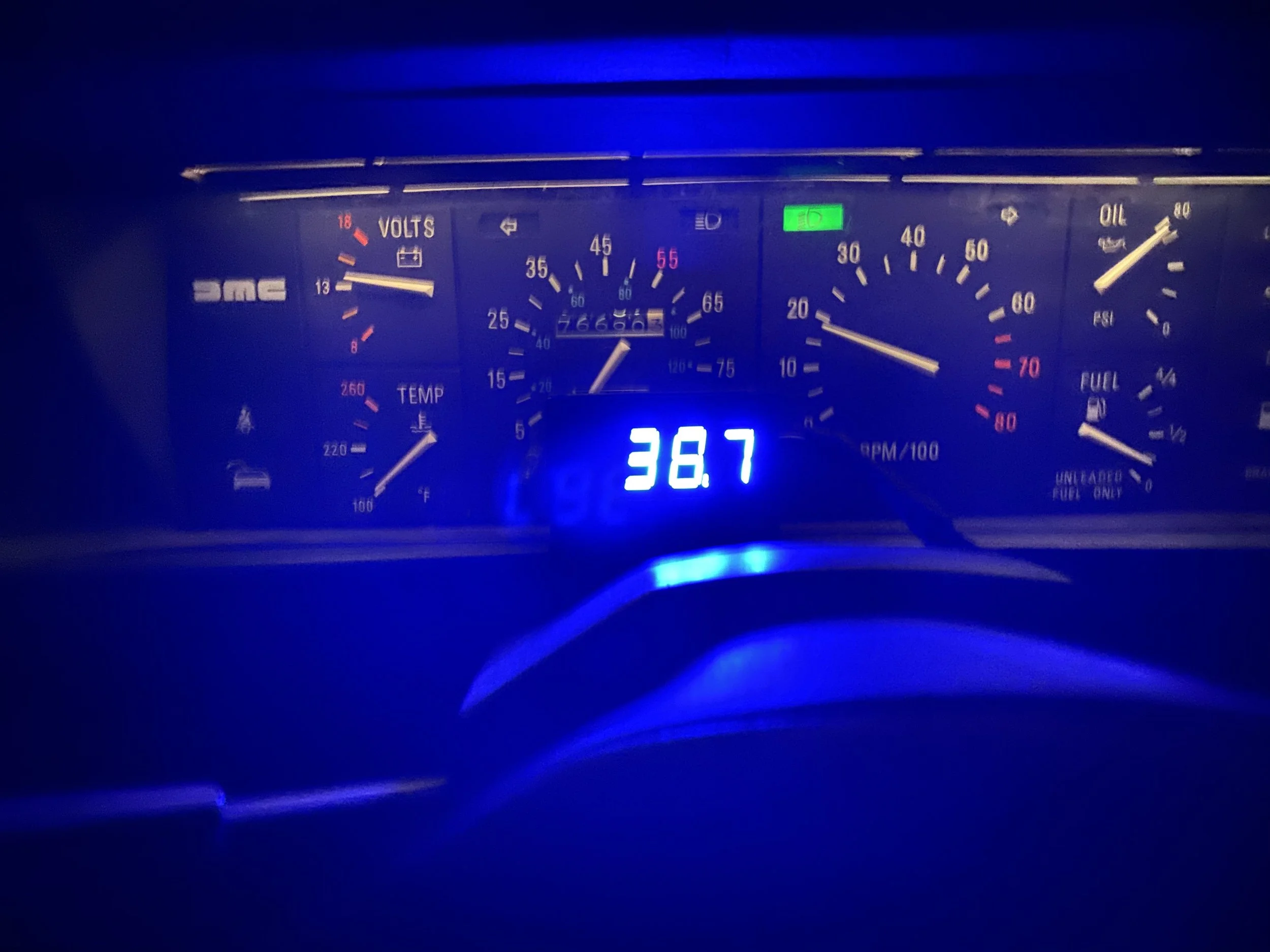
The blue display mounted in the black case with the three-point-one digit software.
The startup animation for the display. Quick and simple, but it’s nice to see when you turn the car on.
Final Result
I’m quite happy with this speedometer. The speed display is rock solid and stable now that I’ve dialed in the exponential filter weight and used a shielded cable from the Hall sensor tot he Arduino. I’m tempted to keep this even after I do my digital dash.
Update October 2019: After posting this on DMCTalk, CriticalB mentioned that I could reduce the overly bright blue LEDs and hide the white/grey case with some black dimming film commonly sold for LED alarm clocks. I bought some from Amazon, and it worked surprisingly well. I had to use double-sided tape to secure it, as the electrostatic adhesion didn’t work at all, but it both brought down the brightness at night and completely hid the white/grey case in daylight.
Black dimming film over the display, secured with double-sided tape, makes the screen easily readable in daylight and not blindingly bright at night.
Parts List
Here are the parts I used. Most of these are available from Amazon in some form, but you may find better prices elsewhere.
Arduino. A simple Uno will do fine. I used a Mega 2560 ($10-$20).
Adafruit LED backpack ($8) and matching seven segment display ($8) in your choice of color.
Porsche 930 VSS ring ($40).
55505 Hall sensor package ($22).
“L” bracket or similar mount for the Hall sensor, such as the 11133 from NAPA ($2).
12v to 5v buck power supply ($12). Amazon describes the one I got as 12v to 5v DC Converter, DROK Voltage Regulator Board Power Supply Module, DC 6.3-22V 12V to 5V 3A 15W Waterproof Car Volt Step Down Buck Converter. You’ll also want a fused connection to the accessory relay.
Fine gauge wire for the Arduino and display.
Heavier wire for the buck power supply connections.
Arduino protoshield or header pins (I used header pins) to connect the wires to the Arduino.
JST connectors (optional), so the wires between the Arduino, display, Hall sensor and power supply aren’t permanent.
Shielded three-conductor wire to run from the Hall sensor to the Arduino ($12)..
Wire loom tape to wrap up all the wires when you’re done.
A case for the speedometer, which you’ll have to fabricate yourself.
A case for the Arduino, if desired.
Files
Arduino Sketch. It’s called DMCShifter because I have some other plans for this setup, but the important code is in SpeedoPulseCounter. The following libraries are required (you can add them from the Arduino IDE):
- MegunoLink (exponential filter for speedometer)
- Adafruit LED Backpack (7 segment display)- Adafruit GFX (7 segment display)
- Atomic (header, for intrerupt safety)