MegaSquirt A/C Idle Up Modification
Joe Angell
The A/C compressor puts a significant load on the engine, which can cause issues with low RPMs when idling. Many cars get around this by increasing the idle when the A/C is on. MegaSquirt can do this too, with a bit of setup..
If all you want to do is increase the idle when the A/C is on, you just need to take the output of the DeLorean’s mode switch and connect it to an input pin on the MegaSquirt. But MegaSquirt can also decide when the A/C should be on or off based on engine state. For example, if the idle drops too low it can turn the A/C off. This requires an output from MegaSquirt that controls a relay installed between the mode switch and the low-pressure switch.
Unfortunately, MegaSquirt II doesn’t have enough inputs and outputs pre-wired for this, but you can modify it to support it. There are a number of digital and analog pins that aren’t used, and which can be exposed as inputs and outputs. This is all explained in the MegaSquirt II Hardware Manual.
Standard DeLorean Wiring
The DeLorean wiring for the A/C compressor is fairly straight forward. When the mode switch is in one of the two A/C modes, it sends 12v from the light accessory-switched green/white wire at fuse 10 along the pink/orange wire to the low pressure switch, and from there to the compressor clutch electromagnet. When the switch is off, the 12v is disconnected and the compressor clutch disengages.
To install full A/C idle up, we just need to run the K/O wire to an input pin on the MegaSquirt (via a circuit that can bring the 12v down to the 5V MegaSquirt uses), then add our own relay on the K/O line.
The relevant portion of the A/C wiring diagram for compressor control and mode switch state.
My wiring digram showing how I installed a relay on the pink wire, passing the pink/orange wire to MegaSquirt for the A/C state and using it as the relay-switched power through the low pressure switch.
Input Circuit
The input circuit is used to tell if the A/C is on. In the DeLorean, this means when the mode switch is set to one of the two A/C positions. You want to tap the pink/orange wire between the mode switch and the low pressure switch. Don’t tap after that (say, between the low pressure switch and the compressor), or you’ll be telling MegaSquirt that the A/C turning on and off when it’s simply the compressor cycling, and you won’t get the results you expect.
The mode switch either provides 12v on the pink/orange wire, or it is floating.. Floating means that it’s not 12v or ground — it’s just not connected. This confuses microcontrollers like the one in MegaSquirt, as random RF noise can cause the pin to randomly read as high and low. To work around this, you need to pull it down to ground (through a resistor) when it’s not connected.
Pages 31-32 of the hardware manual explains how to make a circuit for a 12v digital input, also known as a “going high” input. You cannot use the “going low” circuit here, because the pink/orange wire doesn’t actually ground out but rather floats, as described above. The “going high” circuit requires a few more parts, but it’s not too hard to build.
In short, you wire up a transistor between one of the available microcontroller digital input pins and. The transistor is also connected via a pull-down resistor to ground. This ensures that when the A/C is off, the floating input reads as ground, but when the A/C is on it switches the 12v input to a 5v microcontroller-safe voltage that MegaSquirt can read.
This requires two transistors: a 2200 ohm resistor to protect the transistor base from the 12v input, and a 1000 ohm resistor for the pull down to ground. I didn’t have the 2200 ohm resistor required, so I just used two 1000 ohm and two 100 ohm resistors, since resistor values add together. I used JS5 as my microcontroller input pad.
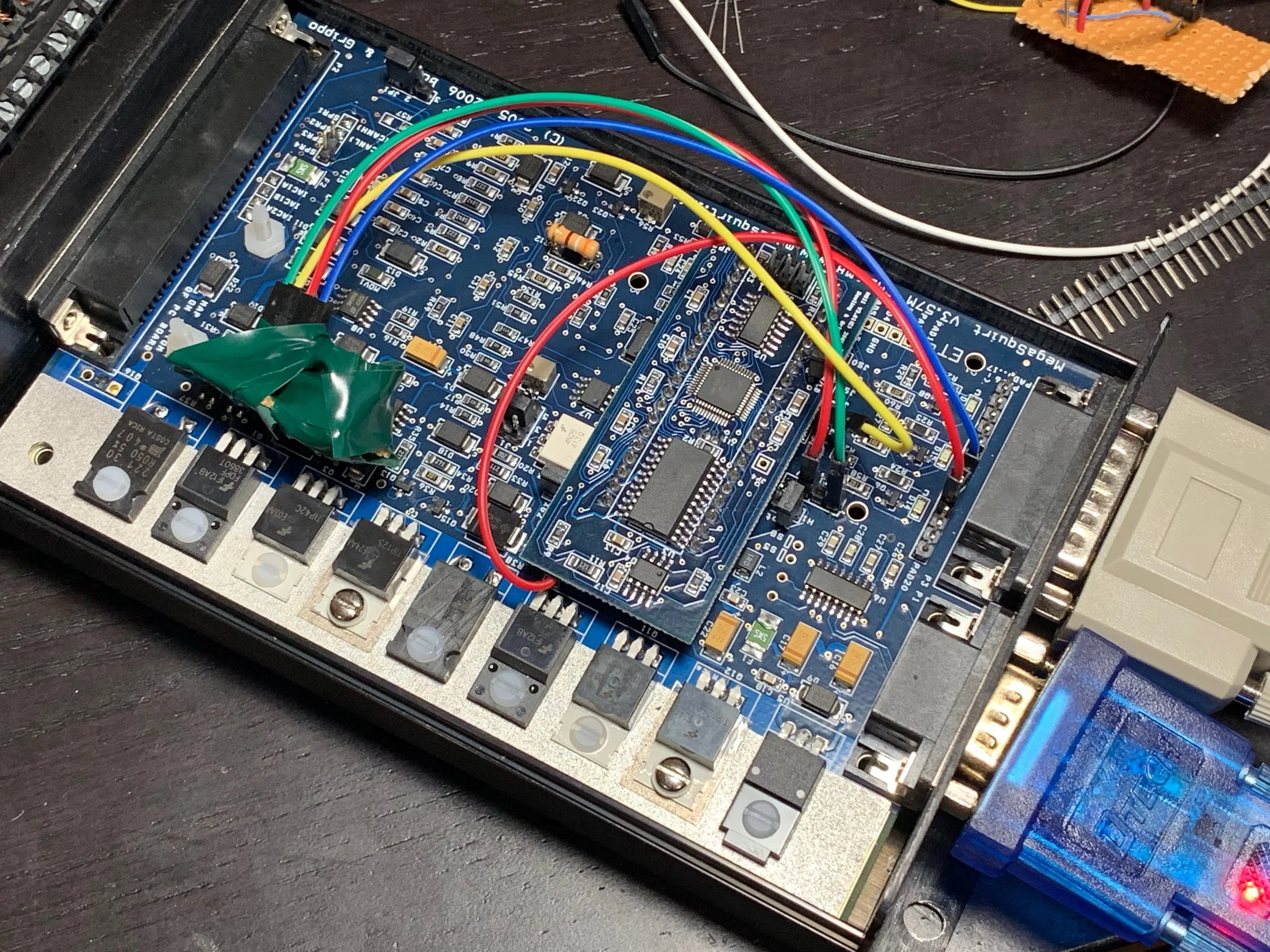
Rather than soldering wires directly to the MegaSquirt board, I soldered header pins. These are commonly used in Arduino projects, and support jumper wires commonly used in breadboards. I run jumper wires wires from these pins to the simple transistor/resistor board I made as per the hardware manual. The nice thing about this setup is that it’s easy to remove and to test different configurations, although there is the small risk that the wires could come loose if I hit a large bump in the road. This seems rather unlikely, though.
To get the input from the car to the pin, I decided to use the DB15 connector. The DB15 pinout is described on pages 78-79 of the hardwire manual, and is intended for expansions like this. Three of the pins are already wired — pins 1 and 2 to ground, and pin 8 to VCC (5v, in this case). I soldered a header strip along the pads for the DB15, and ran a jumper wire from my transistor’s base to PAD13 (pin 4 on the DB 15 connector). I confirmed this was the correct pin with a continuity tester on my multimeter, touching the header pin with one end of the proble and the DB15 port pin with another.
I tested the circuit by connecting MegaSquirt to my JimStim. In TunerStudio, I turned on A/C Idle Up with mostly default settings, then ran a jumper from the base of the transistor to either the ground or 5V header on the JimStim. There’s no 12v header; if you really want to you can touch a wire to the bare end of the 12v power supply barrel connector to get that, but that’s not necessary as 5v works just as well for this test. When attached to 5v, the “AC” light in TunerStudio would light up (after the five second delay I set); when disconnected or at ground, the “AC” light would immediately turn off.
My going high transistor board. The four restores along replace the single 2200 ohm resistor I didn’t have. The other resistor is a pull down, and the jumper wires lead to the MegaSquirt.
The transistor board being tested with the 5v header from the JimStim. Note that the red wire is tied to the wrong pin on the DB15 at this point. Everything else is correct, though.
Another test configuration. Again the pins are not on the correct pads for the DB15.
My initial A/C idle up settings, both for testing and for use in the car.
Output Circuit
A digital output circuit is shown on page 41 of the hardware manual. I took a somewhat simpler approach, but used a MOSFET instead of a normal transistor. MOSFETs are more microcontroller-friendly as they can operate directly at 5v and thus don’t require the extra resistor that is normally used to protect a transistor’s base. I also decide not to use an automative relay, but rather a 5v relay board commonly used for Arudino projects, which is also opt-isolated and doesn’t require a flyback diode to protect the MegaSquirt or the MOSFET when the relay is turned off.
I decided to put the MOSFET outside of the MegaSquirt case, which kept the internal MegaSquirt wiring very simple — a simple jumper run from JS11 to PAD 14 (pin 3 on the DB15 connector). That’s it.
The 5v and ground from the DB15 are run to the DC+ and DC- on the relay board. 5v also goes to the MOSFET, and pin 3 from the DB15 to the gate of the MOSFET. The remaining MOSFET pin goes to the “in” terminal on the relay board, and is what actually turns the relay on and off. To keep the pins from being bent too much or shorting unexpectedly, I soldered the wires to the MOSFET through a small piece of protoboard.
The terminals on the other end of the relay board are the 12v input and the 12v output. The center terminal is the input (“COM” for “common”), and either of the other terminals will be live depending on if the relay is energized (normally open) or not (normally closed); I wanted it on the normal open output so that the relay has to be energized for the A/C to be on. The yellow jumper swaps the behavior of the “in” terminal, so if the switching logic is backwards you can just move the jumper, or change the Idle-up Input Polarity in TunerStudio.
To test the circuit, I set up the Programming Input/Output options in TunerStudio to toggle JS11 based on the coolant temperature. This allowed me to turn the CLT knob on the JimStim, and when it got above 100 degrees it would trigger JS11 to output 5v, which could then be tested with a mutlimeter; when it dropped below that, it would read 0v. To simplify testing I used SPR3 on the DB37 so that I could more easily probe the pins with a multimeter (I had also originally planned on using SPR3 and SPR4 before switching to the DB15. The existing 5v out on the DB15 made it easier to hook up the relay board).
Testing a MOSFET as an output using SPR4 on the DB37. 5v can be seen being read by the logic problem.
The relay board passing through a transistor. Although the board uses 5v, it may draw too much current for the MegaSquirt pin, so using a transistor or (in this case) MOSFET protects the microcontroller.
The input circuit wrapped in electrical tape to keep it from touching something unintended on the MegaSquirt board and shorting it out. The red and blue wires are now properly connected for both input and output on the DB15 pins 3 and 4.
TunerStudio settings for testing the input circuit with the coolant temperature knob on the JimStim.
DB15 Connector
For the DB15 side, I ordered a connector with screw terminals from Amazon. This is much easier to attach wires to than soldering them on, and the screws should hold everything in place just fine in an automotive environment. I also purchased a six foot long DB15 extension cable after discovering that the connector wouldn’t fit over my fuse box near where MegaSquirt mounts behind the driver’s seat. This let me position the end screw terminal connector in the cabin near the evaporator box, rather than running individual wires down the center console.
The DB15 extension cable end and the DB9 tuning cable end just barely fit next to each when plugged into MegaSquirt, and actively push against each other’s housings. But they do stay tight. I had a similar problem on the other end, where both the cable and the DB15 screw terminal connector had screws. Luckily, the connection is very tight, so I don’t actually need to use the screws to keep them secured.
The screw terminal connector also has a GND terminal. This is connected to the metal case around the plug, but that is not actually connected to anything in MegaSquirt, so it isn’t actually useful without further modifications in MegaSquirt.
The MegaSquirt DB15 pinout from page 79 of the hardware manual.
The DB15 connector running to the relay board and the externally mounted MOSFET. The other pink wire is for the input from the mode switch to tell MegaSquirt that the A/C is on.
Car Side Wiring
The car side is just a matter of splicing into the pink/orange wire form the mode switch to the low pressure switch. Luckily, the center console and stack doesn’t need to come out for this, as the wires run through the firewall from under the evaporator on the passenger side.
Running the Wires from MegaSquirt
The first trick is getting the wires from behind the driver’s seat to the front of the car. I could have run individual wires, but there are a lot of pins left on the connector, so I decided to use a DB15 extension cable instead. A 6’ long one was just barely the right length.
The connector just fits between the tray and the back of the seat, after a bit of prying against the wood to make some space. From there I needed to get it through the wooden backing, around the center console and to the front of the car. There was already a hole in the wood for some extra wires, but I something larger to get the DB15 connector through. I used an oscillating saw to cut through the wood. Unlike a reciprocating saw, this uses a blade that pivots a few degrees left and right. This is very useful for flush cuts and detail work where you don’t want the blade to cut too far through the material, such as here where I don't want to risk cutting any other wires. I cut a roughly rectangular hole, and after a bit of massaging I was able to pull the connector through.
Once through the wood I was able to snake it under the center console, over the transmission tunnel and down the passenger side, tucking it under the sides of the console cover to hide it. The next time I take the center console out I may run it along the other wires bundles above the transmission tunnel, but this I fine for now.
The DB9 (black), DB15 extension (grey) and DB37 )silver) all connected to MegaSquirt.
Routing of the grey DB15 cable. A rectangular hole had to be cut to fit the large connector through the wood panel.
The path (yellow) of the DB15 cable from MegaSquart (bottom right, behind the driver’s seat) to the passenger side of the cabin (top left).
Modifying the Car Wiring
The wiring itself was pretty straight forward:
I just had to strip away a bit of the electrical tape around the wires
Cut the pink/orange wire. I installed male and female automotive blade connectors on the wires so that I could go back to stock if necessary.
Cut two lengths of pink wire, crimping them both in the same blade connector. This connects to the side of the K/O wire that runs to the mode switch (easily found by turning on the A/C and testing with cut wire ends with a multimeter). If had K/O wire I would have used that, but I only had pink , and that’s close enough.
Run one of the pink wires to the “COM” connection on the relay board. This is the 12v that is switched by the relay.
Run the other pink wire to Pin 4 in the DB15 connector. This is the sense wire that tells MegaSquirt that the A/C is on.
Cut another length of pink wire, and install a blade connector on one ending, plugging it into the other end of the K/O wire that runs to the low pressure switch.
Connect the other end of the pink wire to the normally open terminal on the relay board. This will carry the 12v from the “COM” terminal when MegaSquirt energizes the relay to activate the A/C.
I used zip ties to keep the wires together, with the eventual goal of using wire loom time once the case was ready.
The K/O wire, with blade connectors already added to the cut wire. The pink wire next to it runs from the low pressure switch to the compressor, and should not be modified.
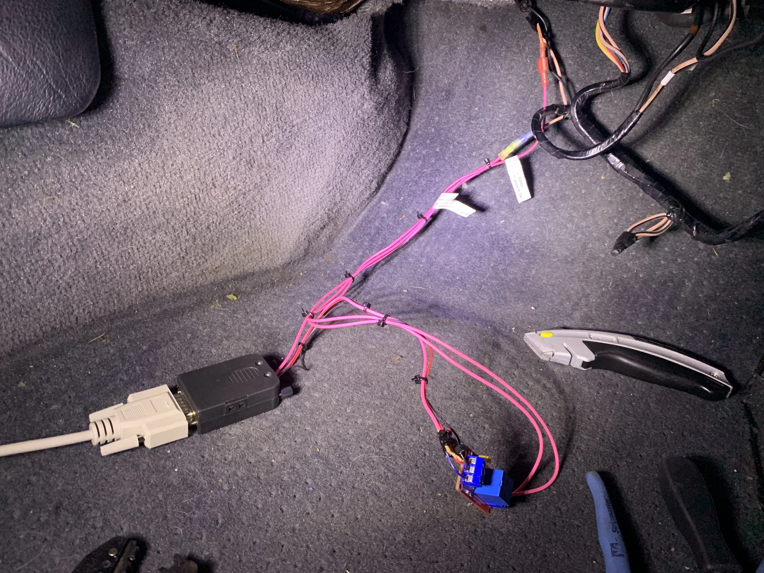
The final wiring from the car’s electronics to the DB15 connector and the relay . The grey DB15 extension cable runs back to MegaSquirt.
A closer view of the relay board and transistor, which will eventually be put in a 3D printed case, but which could be just wrapped in tape instead.
Testing
This is easy: turn the car on, then turn the A/C on. Within five seconds (which is the delay I put into MegaSquirt) the relay should click on and the idle will increase. Turn off the A/C, and the relay should immediately click off. Note that I need the car to actually running to test this, as I told it to turn off the A/C when below 700 RPM, which means simply turning the key to accessory wouldn’t work.
Mounting the Relay and Connector
I had a few options here. Since the relay isn’t in a case, I decided to use my newly-acquired 3D printer to make one. It’s a simple box, so it was a good first project. I added some stand-offs for the relay board, and space on one end for the transistor. I thought about some kind of mount for the transistor board, but it wasn’t entirely clear how everything would lay once it was connected, so I decided to just let it float free in the case.
The final installation wraps the wires in wire loom take and tucks it up behind the center stack, getting it out of the way and keeping it safe.
The relay board screwed into the case. The transistor board just floats freely inside.
The closed box with the relay and transistor inside, and a label so I remember what it is.
Final installation tucked up behind the center stack, with wire loom tape used contain the wires.
I took it for a long drive the next day and it worked perfectly. My idle never went low enough to cause a stalling problem (something I’ve been trying to separately diagnose) and the A/C ran as expected with no issues at all.