Flux Capacitor CPU Meter
An Arduino-based project to convert a Diamond Select Flux Capacitor replica into a CPU activity meter and low memory indicator.
2011 - 2012
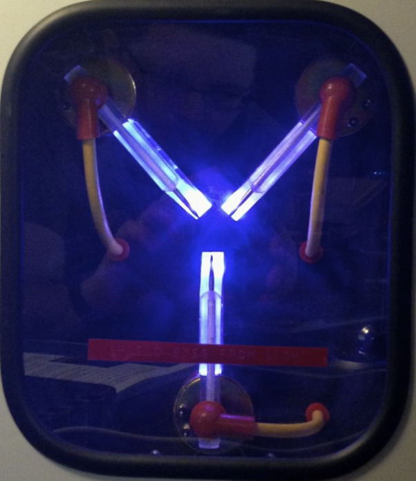
This project turned a Diamond Select Flux Capacitor replicate into a functioning CPU activity meter and low-memory indicator. The LED pulse rate is tied to CPU activity. When available system memory drops below 20%, the lights change color from blue-white to red.
Original Hardware
The original Diamond Select prop features a dial on the front to control the pulse speed of the white LEDs. Three LEDs would go on at a time: first the outermost set, then the middle set, and then the inner set. A set of LEDs would turn on for a period set by the dial, then turn off, and then there would be a slight pause before stepping to the next set of lights. I found the effect rather jarring and distracting, and decided to do something about it.
The prop has three small circuit boards mounted to the back of the main panel. One of the boards has a small micro-controller that is connected to the dial and the two other boards. Each board has three LEDs and are held in place with a single screw per board. The unit normally runs on three AA batteries, which are accessible from the back of the case.
Disassembly
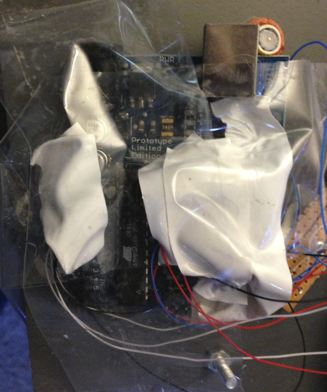
Four screws hold the panel into the case. Once removed, it's just a matter of removing the three screws securing the LED boards, and the four screws holding the battery holder in place. There's not much to it. I wanted to leave the dial in place to avoid having a big hole in the panel, so I left the parts inside the ample case and pushed them off to the side, taping them safely out of the way with packing tape.
Custom Electronics
I used EAGLE to figure out what parts I needed and how I was going to hook them up. This is the first time I'd used EAGLE, but after going through a couple of tutorials I found it was easy enough to use, although slightly arcane at times. Adafruit provides an Eagle library for all the parts they sell, which made layout easy. You can download the
For parts, I used an old Arduino Duemilanove I had lying around as the brains of the unit, and some RGB LEDs from Adafruit. The Arduino has enough PWM-capable pins to let me fade the three sets of LEDs in and out for two colors. In short, one pin controls an LED set's red component, while another pin controls both the green and blue components. Turning off the green and blue pins changes the LED from blue-white to red.
Once I had the LEDs wired up, I was able to program a smooth pulse sequence, where an LED step would quickly fade from off to full intensity, and then slowly fade out. The next LED step would start to fade in before the first one finished fading out completely. The final result is a nice, smooth pulsing effect that isn't nearly as jarring as the original design.
Windows Application
A Windows system tray application is used to control the Arduino. This is a system tray application, sitting unassumingly out of the way with a little black and white icon. For testing purposes, you can manually set the pulse speed and color from within the application, or you can leave it to using the CPU activity and available memory. The application lets you pick any COM port, thus avoiding the need to edit configuration files or recompile with new settings. I tried to make it fairly complete and professional.
Communication is through a simple single-byte serial protocol over the USB cable, which also provides power to the Arduino and LEDs. The high bit (0x80) indicates if the LEDs are to be red or blue-white; the remaining bits specify the pulse speed. Once the state is set, the Arduino handles all updates. If the application isn't running, the LEDs simply pulse blue-white at a constant rate. The also Arduino dumps a lot of information about what it's doing back over the serial port, but this isn't displayed in the application -- communication is one way. LED state is sent once per second when set to monitor CPU activity and/or memory usage, which is also how often Windows Task Manager updates
The Windows application is written in C++ using Windows Forms. This is the first time I'd used Windows Forms, but there is a lot of documentation and it was fairly straight-foward to put together the interface. If I were to do it again, though, I think I'd learn enough C# and implement it that way, as Windows Forms really seems designed to work with C# more than C++.
Future Improvements
I'm pretty satisfied with how this project came out. That said, there are a couple of issues that I would like to address in the future:
- The Windows application doesn't like it if the Arduino is unplugged while it is running, and will simply crash. This doesn't happen very often, though.
- All of the LEDs are updated from the current pulse speed. This means that if the pulse speed changes, the LEDs will appear to "jump" to the new intensities for that pulse speed. I should change the sketch so that once an LED set has started pulsing that it will then fade out at constant rate. The code would also have to handle the LED set being pulsed back on while it's still fading out, but that's simple enough to handle.


In Action
(23 seconds)

Files
- Arduino Sketch (5 KB)
- EAGLE Layout (84 KB)
- Windows Application Source (4.9 MB)